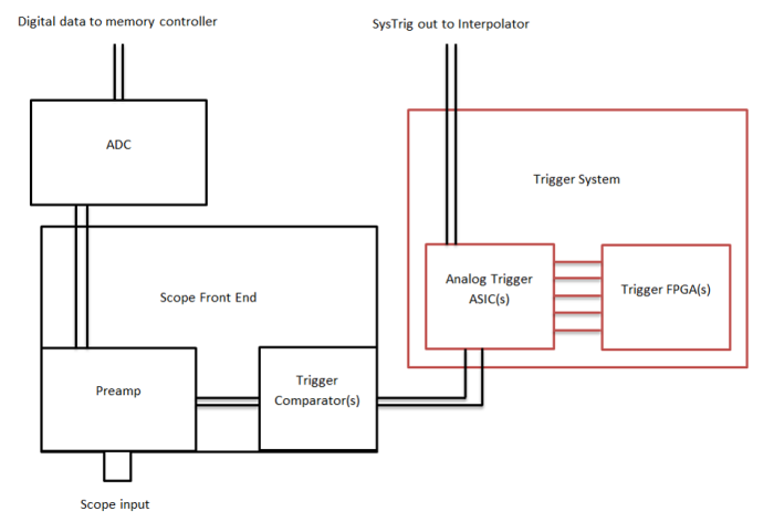
I'm trying to learn more about digital oscilloscopes, especially triggering. Here is how I think the trigger works: Let's say I set the trigger to edge mode, and the level to 5V. When the signal measured then hits 5V, the scope's ADC activates and it starts to sample the signal. Some amount of data points are gathered, and these are plotted on the screen. Then there is a small "dead time" after which the scope again waits for the trigger condition to be met, and the same amount of data points are gathered again. These should now line up with the previous set of samples, and therefore the scope output looks stable on the screen.
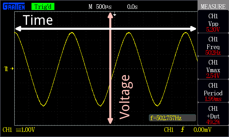
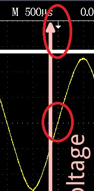
The time axis is something I don't completely understand. I believe that the origin of the grid, where the highlighted dotted lines intersect, is the triggering point. At that point (at "t = 0") the voltage should be equal to the trigger level voltage. Am I correct so far? The thing is, this is not always the case with my oscilloscope. Sometimes the voltage at the origin is not equal to the trigger level, and the signal even drifts slowly to either direction. What causes the signal to drift even if the trigger is set?
Another confusion that I have: I've seen the right side of the origin called the "post-trigger" data and the left side "pre-trigger" data. How is there data from before the trigger, if data gathering starts from the trigger? Shouldn't the trigger point actually be at the very left of the screen?


