0
\$\begingroup\$

Noob oscilloscope user here.

I want to view the voltage rise on my oscilloscope when I connect a device to a 1.5VDC power source, to see how clean the connection is - i.e. how many times the voltage bounces on/off/brownout/etc before stabilizing.

I set the scope trigger to about 200mV, and the input to DC coupling. Measure depth is set to 10M samples at 10MS/sec sample rate. Trigger: single, rising edge. Holdoff is set to minimum value possible (100ns). There is no option to disable holdoff that I can see.

The scope triggers and captures the signal, but there is no rise. It is immediately captured at 1.5V with no rising edge.

I assume since the voltage stays above the trigger level after the initial rising edge, it continues sampling until reaching the end of sample memory, which is 10M samples at 10Ms/sec = 1 sec. So I'm seeing a 1-second-long 1.5v flat DC.

Is there a way to define the length of pre-trigger data to capture? Also I'm confused as to why I don't see a rising edge, since the trigger level is set to only 200mV.

Thanks for any suggestions or explanations.

Here's a screenshot: Screenshot1
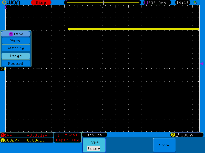
\$\endgroup\$
4
  • \$\begingroup\$ Please provide a model number, and if possible a link to the user manual. \$\endgroup\$ Commented May 15, 2015 at 22:01
  • \$\begingroup\$ Hi, I listed the model in the title of the question but here it is again: Owon SDS-7102. The manual is located here: saelig.com/supplier/owon/sds_series_user_manual.pdf \$\endgroup\$ Commented May 15, 2015 at 22:08
  • 1
    \$\begingroup\$ Have you tried zooming in on the timebase? I dont know that scope but it looks like you are on 50ms/div ... \$\endgroup\$
    – PlasmaHH
    Commented May 15, 2015 at 22:16
  • \$\begingroup\$ Thanks PlasmaHH. That was the issue. It was only capturing at 10M samples/sec. So increasing to the scope's max, 1GS/sec, here's what I got: snag.gy/gfyZM.jpg PERFECT! THANKS! Put your comment in as an answer and I'll accept it. \$\endgroup\$ Commented May 15, 2015 at 22:23

2 Answers 2

2
\$\begingroup\$

You see the little purple jigger at the top of the screen? That shows where the trigger point is in the scope's trace memory. What you want to do is use the horizontal knob to move that to the right, then take another sample. Then use the zoom function to examine the area just before and just after the trigger point. Alternatively, start with a fairly long time base, and get a feel for just how long the connection period is. Then, decrease the time base until the period mostly fills the screen. The problem with doing it this way is that, if something happens after the trace period, there's no way for you to know it.

With the trigger point all the way to the left (in what's called the display window) only data acquired after the trigger event will be displayed. If you move the trigger point all the way to the right, only data acquired before a trigger event will be displayed. Notice that in the manual, the "normal" setting is in middle of the window, although this is obviously adjusted depending on what's important to you.

\$\endgroup\$
2
  • \$\begingroup\$ Thanks for the detailed info. Great to learn about the "T" symbol and how to change the trigger point! \$\endgroup\$ Commented May 15, 2015 at 22:30
  • \$\begingroup\$ You can probably reset the horizontal offset to 0 by pressing in the horizontal knob. \$\endgroup\$ Commented May 15, 2015 at 23:07
1
\$\begingroup\$

For this digital oscilloscope, 'trigger point' doesn't appear to be the same as 'trigger point' for analog oscilloscopes. The digital oscilloscope appears to keep capturing data, and the 'trigger point' (for the digital scope) is more like making a particular voltage of a waveform become aligned with a particular x-axis location on the oscilloscope's display (such as at x = 0, or t = 0, which is along the centre vertical line of the digital oscilloscope screen).

Where-as, for an analog oscilloscope. The trigger level would make the waveform begin at a specific voltage level, which would start at the left-hand-side of the display.

The digital oscilloscope basically remembers values BEFORE the so-called 'trigger point' because it is a digital system, and it has the capability of storing values prior to that 'trigger point'. So I guess for digital oscilloscopes, it's not 'really' a trigger point as such.

\$\endgroup\$

Your Answer

By clicking “Post Your Answer”, you agree to our terms of service and acknowledge you have read our privacy policy.

Not the answer you're looking for? Browse other questions tagged or ask your own question.