0
\$\begingroup\$

schematic

simulate this circuit – Schematic created using CircuitLab

70I am trying to make a circuit in which the switches will determine the outputs for the xor gate however when i used the switches it is giving me the opposite outputs. For example, a 1 & 1 should give a 0 but i am getting an output of 1.

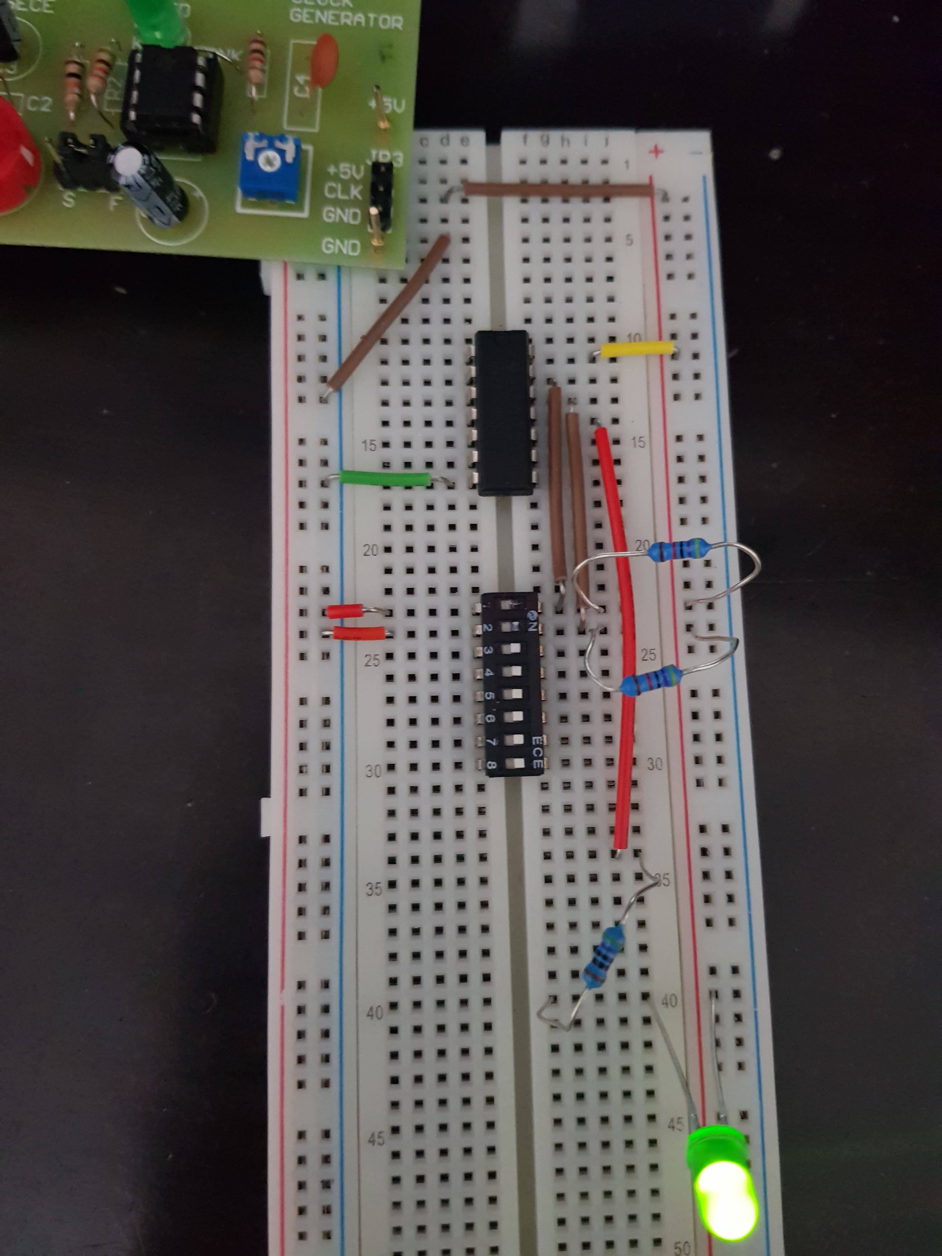
I have attached a picture of my board.

Note the resistors connected to 5v and to switch are 470kohm and the resistor connected to led is 470 omhs.

note that for IC the VCC is on top right and grnd is on the bottom left. Also the top two pins from right after VCC are the inputs and the one below that is the output (HC86 gate).

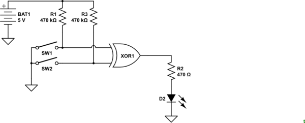
Edit * I am not sure the schematic is correct as I was not given one to work with but I think this is essentially what I am trying to do.
enter image description here

schematic

simulate this circuit

Figure 3. Corrected schematic for OP to verify. [By @Transistor.]

\$\endgroup\$
4
  • \$\begingroup\$ You need to show a schematic. There's a CircuitLab button on the editor toolbar. \$\endgroup\$
    – Transistor
    Commented Aug 26, 2019 at 7:20
  • \$\begingroup\$ See the redrawn schematic, Figure 3. Is that what you're trying to draw? \$\endgroup\$
    – Transistor
    Commented Aug 26, 2019 at 9:13
  • \$\begingroup\$ Yes that is the schematic I was trying to draw. Thanks \$\endgroup\$
    – FZRAM
    Commented Aug 26, 2019 at 14:17
  • \$\begingroup\$ Good. Keep + to the top, GND to the bottom. Use GND symbols to keep things need by avoiding wires all over the place. Make it read left to right (which you did). Try to avoid unnecessary kinks and corners. \$\endgroup\$
    – Transistor
    Commented Aug 26, 2019 at 14:22

3 Answers 3

0
\$\begingroup\$

Your schematic shows not what you have on your breadboard. The LED is actually connected the other way round, i.e. anode is actually at +5V, cathode is connected to gate output via resistor (in addition it should show two separate inputs for the gate).

The LED lights if the output of the XOR gate is LOW.
That's why you get the inverted output compared to what you expected.

\$\endgroup\$
1
  • \$\begingroup\$ Ohh I got it. Thanks for the help! \$\endgroup\$
    – FZRAM
    Commented Aug 26, 2019 at 7:47
0
\$\begingroup\$

You connected your LED from 5V to the gate, so the status of the LED will be the inverse of the output of the HC86.

If the output is 0 -> LED on, if output is 1 -> LED is off.

On the picture the switches are 0+0 so output is 0 and LED on.

\$\endgroup\$
0
\$\begingroup\$

Attach the anode of LED to the output of XOR gate through resistor. Attach cathode directly to the negative rail.

In fact you are getting logic 0 at the output. The LED lights because the LED has anode to +5V and cathode to 0V through resistor, so your LED lights.

\$\endgroup\$
1
  • \$\begingroup\$ thank you I didnt realise that. \$\endgroup\$
    – FZRAM
    Commented Aug 26, 2019 at 7:47

Your Answer

By clicking “Post Your Answer”, you agree to our terms of service and acknowledge you have read our privacy policy.

Not the answer you're looking for? Browse other questions tagged or ask your own question.