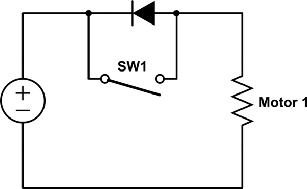
Your circuit doesn't provide any braking because the motor is running free when the switch is open, and won't produce higher voltage than the battery unless it is 'over-driven' to higher speed by an external force.
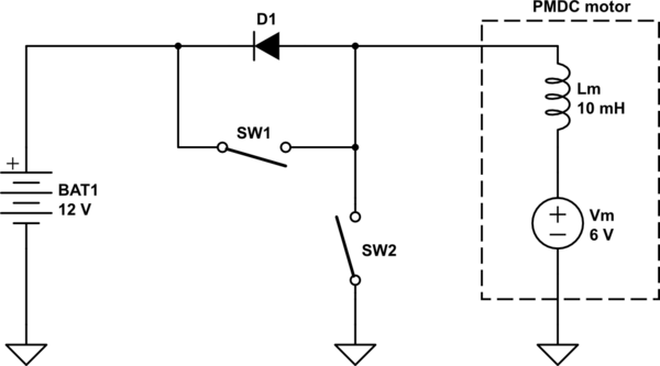
To brake the motor you must put a switch across it, like this:-

simulate this circuit – Schematic created using CircuitLab
When SW2 is closed it 'shorts out' the motor. While the motor is spinning it acts as generator, producing voltage which pushes current through SW2. The current produces torque which brakes the motor. This is dynamic braking, but not regenerative.
However if PWM is applied to SW2 then each time it opens the collapsing magnetic field in the motor's winding inductance creates a 'back-emf' voltage which tries to keep the current going. The current then takes the only path available to it, through D1 into the battery. As well as charging the battery the back-emf current also produces braking torque in the motor.
If the controller uses PWM to control motor speed then this circuit can be 'free', because it uses the same switches that are used in a half-bridge configuration. The only change required is to keep the 'motor' switch open while applying PWM to the 'brake' switch. Most controllers use MOSFETs which have built-in body diodes, so an external diode is not needed either.


