1
\$\begingroup\$

To improve isolation between the input and the other pins of a circuit, I used an MCP6001R SOT-23-5 op-amp which has a pin-out like this:

Footprint of SOT-23-5 Opamp

I am interested by the fact that there is quite some space around pin 4 to do guarding experiments.

However, when I designed the board I made a mistake: I swapped the "-" pin and the "+" pin.

I looked for an op-amp that would have the "+" pin on pin 4, but I could not find any.

As I really want to keep the signal input "isolated" on pin 4, I should either find an appropriate opamp or introduce an inversion in the feedback loop.

Fortunately, I know that I can't do this, but unfortunately I can't think of another simple solution.

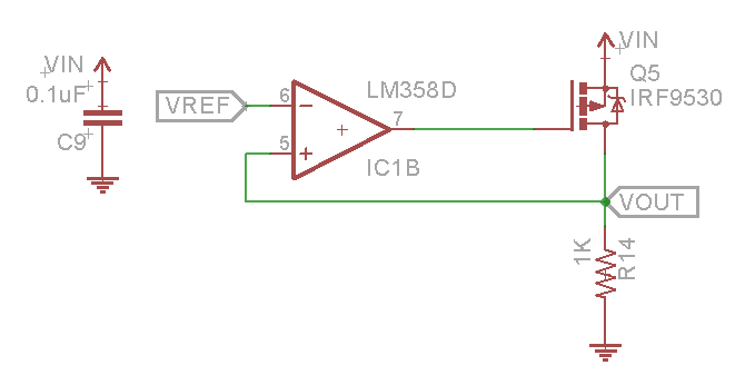
Unstable circuit due to increase in open loop gain source

The above schematic is for showing the principle of applying negative feedback on the "+" pin; it does not show the op-amp that is currently selected.

Questions:

  • Is there an op-amp out there that has the + input on pin4? Ideally in a SOT-23-5 package, but other suggestions are also welcome.
  • Or is there a high impedance analog follower/buffer (< 1 pA input current) at a reasonable cost?
  • How would I introduce a simple inversion in the feedback loop on the positive pin without breaking the stability?

It does not have to be a follower; inverting is fine too, and the amplification does not have to be 1, it can be smaller.

My input signal is a low frequency, high impedance source.

\$\endgroup\$
3
  • \$\begingroup\$ Follow up: the board was redesigned to solve the design error. and I moved to a THT component to be able to "guard" the + input. I did not find a suitable way to us the - input as the "guarded" high-impedance input. \$\endgroup\$
    – le_top
    Commented Dec 12, 2021 at 22:39
  • \$\begingroup\$ If you have gotten to the point that you're trying to use guard rings and such, I hope that you're aware of the need for absolute cleanliness. You need to be very aggressive (even obsessive) about flux removal. Assembled boards should be handled with gloves - the deposited oil from a fingerprint can be an issue if the currents are low enough. \$\endgroup\$ Commented May 20, 2022 at 13:22
  • \$\begingroup\$ Yes, cleanliness is also important with guard rings, but "dirt" may build up over time anyways. "Absolute" cleanliness does not exists, but there are several grades of cleaning. \$\endgroup\$
    – le_top
    Commented May 21, 2022 at 15:13

1 Answer 1

1
\$\begingroup\$

The input bias current is in the 10-100nA range. This means that the source would have to have an impedance with at least that. The LM358 does not need to be guarded, because it's input bias current does not support an application that would require a low leakage trace. enter image description here

Guards are used when the leakage through the PCB is high enough that it affects the signal, and typically is used in applications that have source impedance's below 10pA (at this point, the PCB becomes a conductor).

Edit:

This opamp will have poor results with a PH meter. Get one with the highest input bias current you can find, with the price that works for you. Single opamps in 8 pin packages usually work better for guarding as they have NC pins. Most op amps that have low input bias currents will also have pins that support guarding. Most opamps that have a low input bias current will also have layout guidelines for guarding.

More Edit: If your running a PH meter, the guard trace would look like this:

enter image description here

enter image description here Source: https://ww1.microchip.com/downloads/en/DeviceDoc/21733j.pdf

\$\endgroup\$
6
  • \$\begingroup\$ Ok, sorry if the schematic confused you - I borrowed it from another question on stackoverflow. The OPAMP I selected was MCP6001R . The schematic is just showing the principle of inverting the signal so that the negative feedback is happening through the "+"-input of the opamp. The application is for measuring pH. It's not the PCB that becomes a conductor, but the "dirt" that is on it - generally the flux that is leftover from the cleaning tub that accumulates flux throughout production. Generally DIPs are used - if not leakage problems are observed. So I'm trying something else here. \$\endgroup\$
    – le_top
    Commented Sep 27, 2019 at 21:08
  • \$\begingroup\$ The MCP6001R is good, and has layout guidelines for guarding. You should provide attribution if you ever 'borrow' something, its a good internet practice. It's also good to mention the application and what you really intend to do. I edited my question about guarding \$\endgroup\$
    – Voltage Spike
    Commented Sep 27, 2019 at 21:15
  • \$\begingroup\$ I updated the question with information about the source of the image. The guarding recommendations are not satisfactory - the SOT-23-5 package has the right spacing, but unfortunately on the '-'-pin. And we're trying to keep the footprint as small as possible. \$\endgroup\$
    – le_top
    Commented Sep 27, 2019 at 21:35
  • \$\begingroup\$ "we're trying to keep the footprint as small as possible" why? \$\endgroup\$ Commented Sep 28, 2019 at 2:18
  • \$\begingroup\$ (1) We try to keep it small because of space constraints. (2) We've tried guardrings, it was not satisfactory. Currently the pH-input is aerial to avoid issues. (3) If guarding would be acceptable, it is the "+"-input that needs to be guarded, not the "-"-input . The "-" input is normally taking the feeback from the output to create an inverter or non-inverting amp (with a resistor from "-" to the reference). The guardring example from microchip is not appliable as it is as if the signal arrives on the "-"-input through anything but a PCB wire. \$\endgroup\$
    – le_top
    Commented Sep 28, 2019 at 8:55

Your Answer

By clicking “Post Your Answer”, you agree to our terms of service and acknowledge you have read our privacy policy.

Not the answer you're looking for? Browse other questions tagged or ask your own question.