1
\$\begingroup\$

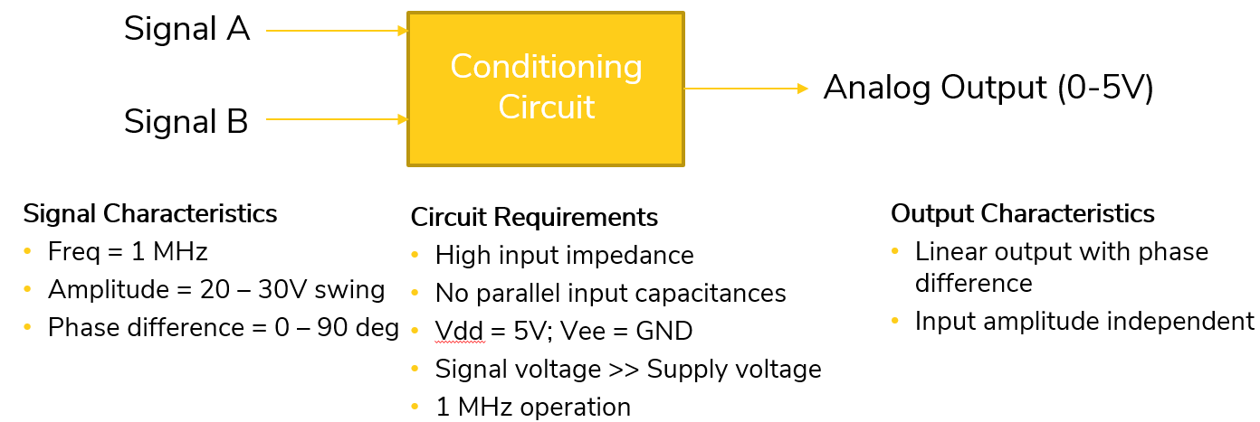
I am looking for a circuit that can translate phase difference of two sinusoidal signals (operating at ~1MHz) to analog voltage swing of 0 - 5V.

The signal A & B comes from the capacitors of two different RLC circuits.The conditioning circuit should not load the circuit as it will change the RLC filter circuit operating point.

I could think about digitizing sine signal + EXOR + filtering but, the RLC capacitor that I am using is about 50pF and using MOSFET for digitizing didnt help as gate input capacitance did change the operating point of the previous stage.

Another option, I was thinking is using a voltage follower opamp + EXOR + filter and I am looking for opamps that can have inputs > 20V with supply voltage of 5V and operating at >1MHz. Any ideas?

Additionally, I came across CD4046B, but I believe that it also needs digitizing before it is fed into the signal & comparator Inputs.

Thanks in advance!

enter image description here

EDIT1:

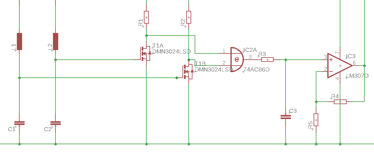
Below is a rudimentary circuit (Please ignore part numbers). If the loading is limited to a few 10uAs, then I beleive the operating point would not shift that much.

enter image description here

\$\endgroup\$
17
  • 1
    \$\begingroup\$ Please provide a complete circuit with the RLC's \$\endgroup\$
    – Voltage Spike
    Commented Sep 30, 2019 at 15:35
  • \$\begingroup\$ XOR gate is simple with buffered signals. then LPF gives DC. But not bipolar in phase with voltage, so show impedance specs of all expected interface signals and purpose. 20~30V sounds like an IAPS \$\endgroup\$
    – D.A.S.
    Commented Sep 30, 2019 at 15:41
  • 1
    \$\begingroup\$ It's impossible to measure a circuit without loading it somehow; what amount of loading is tolerable? \$\endgroup\$
    – Hearth
    Commented Sep 30, 2019 at 15:45
  • \$\begingroup\$ Is this homework? \$\endgroup\$
    – winny
    Commented Sep 30, 2019 at 15:48
  • 1
    \$\begingroup\$ The 4046 will take fractional-volt analogue signals into the comparator. \$\endgroup\$
    – Andy aka
    Commented Sep 30, 2019 at 17:26

1 Answer 1

0
\$\begingroup\$

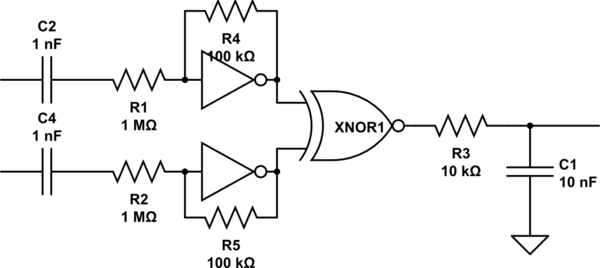
schematic

simulate this circuit – Schematic created using CircuitLab

\$\endgroup\$
1
  • \$\begingroup\$ Yes Indeed. Thanks :) \$\endgroup\$
    – JSr
    Commented Oct 1, 2019 at 15:40

Your Answer

By clicking “Post Your Answer”, you agree to our terms of service and acknowledge you have read our privacy policy.

Not the answer you're looking for? Browse other questions tagged or ask your own question.