0
\$\begingroup\$

I have a ribbon cable that is carrying four signals (each about 5V in amplitude and 1-2 Hz) and a ground wire between a DAC and four op amps.

The op amp outputs are amplifying the signals to 30 V and dropping across really substantial 5 Gohm resistors.

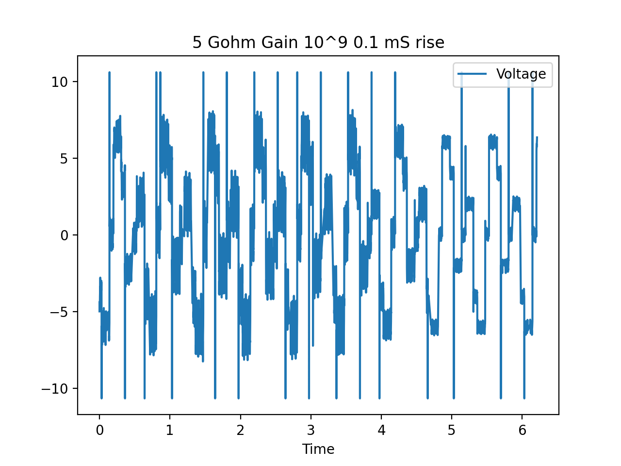
Because the load is so big, I'm using a current multiplier (model Keithley 427) to check that the current is following the voltage in the resistor. The output is fairly noisy as you can see in the attached image. Current multiplier outThe weird thing is, the noise on the output of the current amp is reduced if I press on the ribbon cable that's carrying the signals from the DAC to the op amps. In the last plot, you can see the noise is a lot less around the 4.5 s mark where I start pressing on the cable.
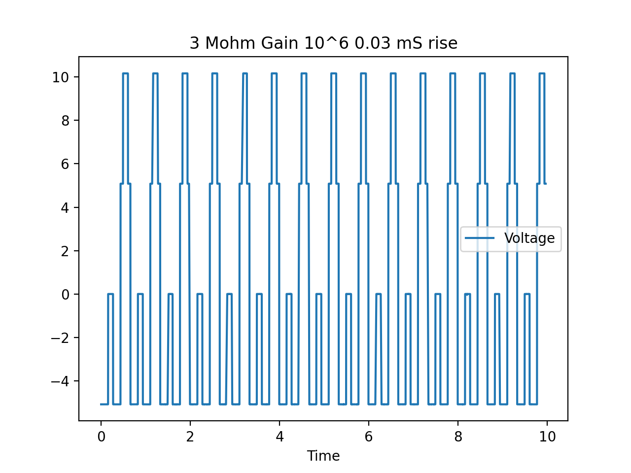
The noise is barely there for smaller loads as you can see in this picture of the current multiplier output for a 3 Mohm load Current multiplier out 3 Mohm
The ribbon cable is unshielded, so I thought it was possible by pressing the cable onto the metal table, I was blocking some interference or capacitive effect between the wires or from the environmental noise. I tried adding some homemade shielding by wrapping the cable in aluminum foil and electrical tape and grounding one end of the foil, but it didn't produce a noticeable difference.

The wires are quite thin (AWG 28 I believe). I have heard some people say that for high frequency AC, you should place a ground wire between each signal on the ribbon cable, but I'm not sure it would do anything for signals in the 1-10 Hz range. I'm quite sure that the connections between the wire ends and their anchor points are solid.

Any ideas you have for why putting pressure on a ribbon cable would reduce current noise for small currents would be greatly appreciated.


\$\endgroup\$
5
  • \$\begingroup\$ Did you ground the shielding at one end? \$\endgroup\$ Commented Dec 18, 2020 at 15:59
  • 2
    \$\begingroup\$ A detailed schematic per channel would allow someone skilled enough to predict the level of noise whereas pictures of the noise with no Y scale information have no meaning. \$\endgroup\$
    – Andy aka
    Commented Dec 18, 2020 at 16:10
  • 1
    \$\begingroup\$ Also consider that pressing the wires to the metal table, especially with very thin jacket material, creates significant capacitance. \$\endgroup\$
    – rdtsc
    Commented Dec 18, 2020 at 16:50
  • \$\begingroup\$ You are a big capacitor. Pushing the cable down decreases the distance between those wires and your body, thus increasing your capacitive coupling. \$\endgroup\$
    – Kyle B
    Commented Dec 18, 2020 at 17:16
  • 1
    \$\begingroup\$ If the source resistance is 5G adding a few pF of capacitance creates a pole in the low Hz. \$\endgroup\$ Commented Dec 18, 2020 at 17:55

1 Answer 1

0
\$\begingroup\$

The weird thing is, the noise on the output of the current amp is reduced if I press on the ribbon cable that's carrying the signals from the DAC to the op amps. In the last plot, you can see the noise is a lot less around the 4.5 s mark where I start pressing on the cable.

Not surprising, you are introducing a few pFs or more of capacitance to the system when you touch the outside of the ribbon cable, this most likely creates a low pass filter in conjunction with the amplifier. But it would be hard to know what is really going on here because modeling your body's impedance and connection to the world would be difficult. The connection is capacitive however.

What you should do is use a shielded cable if possible. One such method of shielding would be to acquire some grounding braid and either construct a new cable with the ribbon cable inside. Use copper because the end can be soldered to much better than aluminum, the connection one end should suffice and it should be low impedance to the ground of the PCB.

enter image description here

Considering that the aluminum foil didn't help at all, you might want to consider a completely different wire harness, a coaxial connection that is shielded would ensure that RF would not likely affect the signal.

Another problem might be your grounding system, as common mode voltage noise from poor grounding between two PCB's could be a problem.

\$\endgroup\$

Your Answer

By clicking “Post Your Answer”, you agree to our terms of service and acknowledge you have read our privacy policy.

Not the answer you're looking for? Browse other questions tagged or ask your own question.