4
\$\begingroup\$

I will work on a small project where an SSI-output data (angle data) of a rotary-encoder will be read by a micro-controller board (such as an Arduino board) and the micro-controller will then send this data to the PC via USB port. The distance between the encoder and the Arduino board/PC is not more than six meters.

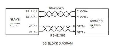
These types of encoders use differential RS422/RS485 electrical interface, one pair for data and another pair for the clock as follows:

enter image description here

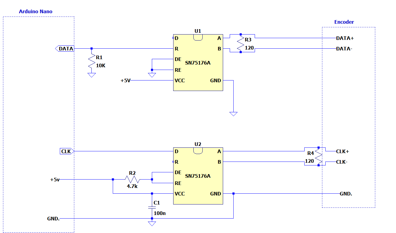
I made a drawing for this particular implementation and the signal chain will look like the following:

enter image description here

The controller board is sending the data to the PC via USB. The PC is earth grounded, meaning its motherboard all the way is connected to the chassis and then to the mains earth. The Arduino board is powered also through the USB.

U1 and U2 are two of these Differential Bus Transceivers(seems there is no galvanic isolation). So these transceivers will be powered by 5V supply or from the Arduno board's 5V terminal. The transceivers and the board will have common ground as depicted in the above diagram.

On the encoder end however the encoder can be powered by a separate power supply(at least that is the plan). In the diagram encoder ground(also the encoder supply ground) is floating wrt controller ground.

My questions are:

  1. Should the encoder ground better be directly wired to the controller ground via a dedicated wire?

  2. If I use the same supply for the transceivers and the encoder, does it matter the location of the power supply? Can the encoder's power supply be remote to the encoder?

  3. Where should be termination resistors?

I came across this article but it is rather confusing.

EDIT:

A more detailed diagram:

enter image description here

enter image description here

\$\endgroup\$
4
  • 1
    \$\begingroup\$ Side note: with a 6m cable, termination resistors should be used on the ends of the bus signals to eliminate reflections. So one at µC Data diff pair, and one at Encoder CLK diff pair. \$\endgroup\$
    – rdtsc
    Commented Oct 24, 2019 at 14:01
  • \$\begingroup\$ If we dont know the characteristic impedance of the pairs would 100 Ohm suffice for termination? 100 Ohm results 50mA. Would it violate the current limit for the transceiver? \$\endgroup\$
    – floppy380
    Commented Oct 24, 2019 at 14:23
  • 1
    \$\begingroup\$ Rule of thumb: DC coupling always needs [some kind of] ground. \$\endgroup\$
    – filo
    Commented Oct 29, 2019 at 16:26
  • \$\begingroup\$ By the way, I only downvoted one of these. \$\endgroup\$
    – Voltage Spike
    Commented Oct 30, 2019 at 4:35

4 Answers 4

4
+200
\$\begingroup\$

In short: A ground is not needed, because of RS485's characteristics. Isolation is in most cases best.

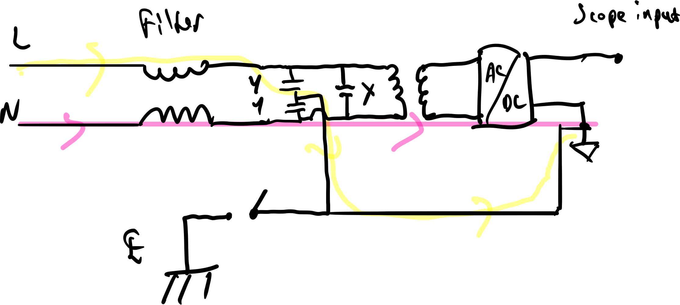
TIA/EIA 485 specifies that no more than ±7V of potential between the grounds of two separate devices (shown as GPD below).

The correct method for designing a differential data link is without ground wires. For ground potential differences higher than the specified ±7V in EIA-485, use transceivers with high-common-mode capability, or isolated bus transceivers.

enter image description here
Source: https://www.planetanalog.com/signal-chain-basics-84-why-rs485-does-not-need-ground-wires/

In some industrial applications, it is entirely possible to have large ground swings between different locations. This can be measured by using a multi meter between the two locations grounds. It should not exceed 7V (in DC or AC modes). If it does, then to stay withing spec, isolation will be needed.

Should the encoder ground better be directly wired to the controller ground via a dedicated wire?

The encoder ground should go back to the power supply, if the power supply is remote from the Arduino, then it is not necessary to tie the grounds together (assuming that there is less than ±7V between Arduino and encoder as described above.

IF the for the encoder is ran back to the arudino and not tied to a power supply on the other end (or the power supply is at the arudino), then the design above should also work (assuming that common mode noise from cable resistance is acceptable (large currents through long cables can cause ground bounce, and the current is dependent on the encoder's current). Cable voltage drop is also a concern if the power supply is located at the Arduino.

If I use the same supply for the transceivers and the encoder, does it matter the location of the power supply? Can the encoder's power supply be remote to the encoder?

It really depends on the resistance of the cables between the encoder and transceiver/Arduino. If the power supply is located on the Arduino end then the cable loss needs to be accounted for.

For example: 22AWG has 0.053Ω of loss per meter. IF the encoder draws 10mA of current, that is a only 5mV of loss for 10m of wire. 100mA and it's ~50mV, More than 50mV and it could be a problem.

So there are a few options, larger cable size, or put the power supply at the encoder, which is fine for RS485 (as long as the grounds are within tolerance)

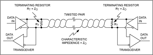
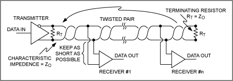
Where should be termination resistors?

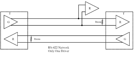
For an Rs422 configuration, what you have is fine (the diagram below has data below and clock above, opposite from yours), a termination resistor should go on the master receiving side and on the slave device (the encoder) it should also be on the receiver.

enter image description here
Source: https://en.wikibooks.org/wiki/Serial_Programming/RS-485

If using only one RS845 device, a resistor on the encoder end, and on the arudino end is appropriate, as shown below

enter image description here
Source: https://www.maximintegrated.com/en/design/technical-documents/tutorials/7/763.html

If you were to use multiple encoders, then you need a resistor on the last device and on the master (Arduino).

enter image description here
Source: https://www.maximintegrated.com/en/design/technical-documents/tutorials/7/763.html

\$\endgroup\$
1
  • \$\begingroup\$ Comments are not for extended discussion; this conversation has been moved to chat. Any conclusions reached should be edited back into the question and/or any answer(s). \$\endgroup\$
    – Dave Tweed
    Commented Oct 30, 2019 at 20:34
1
\$\begingroup\$

As the tranceivers are not isolated, they allow for the bus wires to be 7V below it's GND pin and 7V above it's VCC pin.

This means that there can be no more than 7V of potential difference between GND of this board and ground of the encoder.

As this board has it's ground potential on earthed PC chassis via USB connection, it means that the encoder ground must also be connected to same earth potential via some route, with suitably low impedance which won't allow more than the given +/- 7V difference between them.

1) Based on above, the encoder cannot float with reference to controller. If the encoder is powered with a separate floating power supply at the encoder side, and this supply or encoder has no other reference to earth potential, then it means that there should be a ground wire from tranceiver board to encoder to keep their potential between both ends the same. There should be no current flowing in this wire during normal use, as it is just to keep their potential same. If the separate power supply is not floating but has a ground reference, a separate ground wire between devices may not be necessary. You can always choose a connector and cable so that grounding can be configurable, so you can decide later on to either connect the grounds or leave it disconnected, perhaps with a solder bridge or jumper.

2) If using same supply for both encoder and controller, then there already will be a ground connection between controller and encoder grounds. The power supply location does not matter if it is near encoder or controller. Due to the current flowing in the ground wire there will be some small potential difference between the ends, but you can ignore this as long as the voltage drop is not too much and can still provide enough voltage to the remote end for proper operation. But bear in mind that controller ground is still earthed via PC USB ground connection to the controller, even if controller is powered from a separate supply instead of +5V from the USB.

3) The tranceiver driver portion can drive up to a 60mA load or up to 54 ohms, or about 110 ohms termination on both ends. As the transmission lines are only unidirectional and only between two devices as a point-to-point connection instead of a multi-receiver bus, it is often enough to just terminate at thet receiver with the characteristic impedance of the wire. It is also just as common to terminate both ends of the transmission line, so in this case the termination resistors would be right at the tranceiver chip pins. So draw the resistors at the chip, and you can omit the transmitter termination resistor if you find out it is not necessary, or put a jumper or solder bridge to enable/disable it.

Quote from TI application note slla070d.pdf page 18:

Commonly RS-422 and RS-485 system configurations are presented without a separate ground wire. Laws of physics, however, still require a solid ground connection to ensure error-free communication between drivers and receivers.

Quote from "Understanding EIA-485 Networks" by Contemporary Controls:

The standard clearly states that generators and receivers require a return path between circuit grounds at each end of a connection. This return path could be an actual wire in the cable connecting each of the logic grounds together or earth can provide the return path by having each logic ground returned to earth.

Quote from Integrity Instruments Application Notes Release 1 :

Grounding is essential to reliable operation of any RS-485 network. It is also the most overlooked and least understood. The easiest way to ground your RS-485 network is to simply use “Earth” ground as your return path. Although easy this may not be the best method for grounding your application, because current leaking from equipment, electro-static discharge (ESD), and lightning all drive current through this path which results in high noise content. The reason for this increased noise level is due to the fact that “Earth” ground presents a relatively high resistance. RS-485 is designed to operate normally with a ground potential difference of +/- 7 Volts. ... A good way to reduce this ground and to hold this ground potential difference within standards is to run a third wire

Quote from Robust DataComm appnote 5, supposedly quoting the RS485 standard itself. (Link to appnote):

"Proper operation of the generator and receiver circuits requires the presence of a signal return path between the circuit grounds of the equipment at each end of the interconnection. The circuit reference may be established by a third conductor connecting the common leads of devices, or it may be established by connections in each using equipment to an earth reference."

\$\endgroup\$
1
  • \$\begingroup\$ Please explain the downvotes, and I'll improve the answer. I will improve it soon anyway, due to all the information I found on the grounding to back my claims up. But in short, when PC side is earth referenced, the encoder needs earth reference too, either via earthed power supply, or in case of floating/unearthed power supply, from the PC side with the ground reference wire. \$\endgroup\$
    – Justme
    Commented Oct 30, 2019 at 6:21
0
\$\begingroup\$

It's simple. Yes, you need a gnd connection so you can ensure common mode is not floating away out of the receiver ratings. The gnd connection may not necessarily be a good one, short or whatever, but it has to be there.

The only exclusion is when you have some other weird way to ensure that it does not float, like maybe connecting gnd on one side to an isolated vcc on the other side. But it's weird and takes very careful analysis of both sides.

One more thing. There is a standard way to handle encoders: provide power (5V and GND) in the same cable where the communication goes. Anyway on the encoder side there is nothing electric. A kind of a dead end.

\$\endgroup\$
-1
\$\begingroup\$
  1. You should always have a CONNECTION (not necessarily a wire) since it is not galvanically isolated. No need for a dedicated ground wire though unless battery powered or one end is not earthed. That's what article you linked is saying.

  2. Does not matter. That's what decoupling capacitors are for.

  3. With RS422/RS485, parallel termination is used, so it goes next (ideally past) the last receiver in the daisy chain.

\$\endgroup\$
15
  • \$\begingroup\$ I was just updating with a more detailed diagram. I came across an example and draw a diagram. What do you think about this?: i.sstatic.net/VULz5.png I dont know the purpose of R1 and R2 and DE RE. \$\endgroup\$
    – floppy380
    Commented Oct 28, 2019 at 13:42
  • \$\begingroup\$ RE and RE are enable signals for transmitter and receiver. Used for RS485 when comms are half duplex. You should be looking up what pinouts mean in the datasheet since pin names are not universal. \$\endgroup\$
    – DKNguyen
    Commented Oct 28, 2019 at 13:44
  • \$\begingroup\$ R1 is to prevent a floating signal when the receiver is disabled. Not necessary if the transceiver does not go high impedance when disabled though. But that is not the case for this chip. See Table 3. Receiver Function Table of TI datasheet. \$\endgroup\$
    – DKNguyen
    Commented Oct 28, 2019 at 13:45
  • \$\begingroup\$ Based on what you say, is the location of R3 and R4 termination resistors correct here?: i.sstatic.net/zuFMw.png \$\endgroup\$
    – floppy380
    Commented Oct 28, 2019 at 13:51
  • \$\begingroup\$ @floppy380 Yes. \$\endgroup\$
    – DKNguyen
    Commented Oct 28, 2019 at 13:52

Your Answer

By clicking “Post Your Answer”, you agree to our terms of service and acknowledge you have read our privacy policy.

Not the answer you're looking for? Browse other questions tagged or ask your own question.