0
\$\begingroup\$

Currently, I have a board that powers 4 DC fans. A PWM signal is received from an external microcontroller to control the fan speeds. Unfortunately, the microcontroller sometimes fails to send the PWM signal, and I can not change it at this stage. When the PWM signal is not received the fans ramp up to maximum speed due to an internal pullup resistor in the fans. I want the fans to default at a speed anywhere between 20% and 50%.

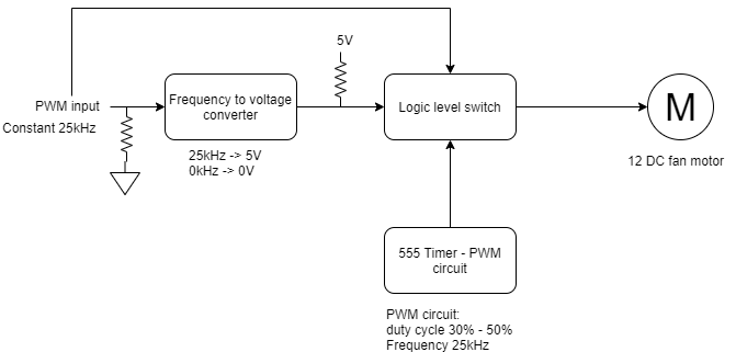
I would like to make changes to this board by adding a default PWM signal which drives the fan speeds when no external PWM signal is received.

I have the following constraints and specifications:

  1. All PWM signals have a frequency of 25kHz

  2. I have 12V available to the board.

  3. The board is tiny (the chosen components must be small and few).

  4. The budget is low (the cheapest viable solution is prefered).

Below I have made a diagram of how I want to solve this problem. I have a few questions:

  1. Is there a simpler way of solving this problem?

  2. Is the 555 timer a good option for a PWM generator?

  3. What logic level switch would be appropriate for a PWM signal?

  4. How will I be able to convert a 25kHz frequency to 5V? (IC suggestions?)

  5. Any advice, comments, critiques, component suggestions will be much appreciated.

enter image description here

\$\endgroup\$
2
  • \$\begingroup\$ Did you make this original board that fails to send the PWM signal sometimes? Why don't you just correct the error in the firmware? \$\endgroup\$
    – DKNguyen
    Commented Nov 19, 2019 at 0:24
  • \$\begingroup\$ I need the DC fans to work properly in the case of the original board failing/ crashing. Unfortunately, firmware access or hardware access to the original board is not an option. I can only make a new board that interfaces between the original board and the fans. \$\endgroup\$ Commented Nov 19, 2019 at 5:25

1 Answer 1

2
\$\begingroup\$

2) yes
3) what is PWM voltage level (coming from MCU)?
4) Since you don't really need precise frequency to voltage conversion, a simple RC high pass filter with one diode rectifier may be enough to define PWM is present or no (you asked for cheapest). Another way is to use watchdog ICs.

\$\endgroup\$
3
  • \$\begingroup\$ There should also be a grounded cap after the diode to get a good DC signal, just a diode would give you a pulse. Also the 555 has a Reset input pin that might be useful with a simple DC enable/disable signal. \$\endgroup\$
    – Nedd
    Commented Nov 19, 2019 at 1:02
  • \$\begingroup\$ Hi Alex, 3) The PWM level is 5V. I am thinking of placing a 5V regulator on the board as well in order to power the IC's. 4) How could you do it with a watchdog? Does the watchdog just send a pulse as a response? \$\endgroup\$ Commented Nov 19, 2019 at 5:28
  • \$\begingroup\$ Maxim gives us example: maximintegrated.com/en/design/technical-documents/app-notes/4/… \$\endgroup\$
    – Alex Life
    Commented Nov 20, 2019 at 17:44

Your Answer

By clicking “Post Your Answer”, you agree to our terms of service and acknowledge you have read our privacy policy.

Not the answer you're looking for? Browse other questions tagged or ask your own question.