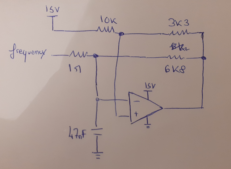
In order to get this Relaxation Oscillator or any for that matter, is to have both inputs Vin+- to have the same swing and average voltage for a 50% square wave.
This means if the output swing is. 2 to 13V for BJT type OA or 0 to 15 V for a CMOS then the Vref. Input must be Vcc/2 and not 15V as shown. Then you get 50% duty cycle. Any change in this offset changes the duty cycle.
The Voltage divider Vout to Vin+ thus determines the swing from this average voltage. What is shown is 3.3/(3.3+1) or about 3/4 full swing exponential triangle. Now the CMOS Schmitt Inverter OSC uses a hysteresis of 2/3 full square swing for the triangle..
Then with +/- 1/3 swing same as the 2/3 hysteresis, the ramp is fairly linear but instead of 64% it is 66% but depends on tolerances with slight exponential response T=RC for f~ 1/2T. Reducing the hysteresis increases the frequency just like changing the RC value.
SIMULATION

