2
\$\begingroup\$

I am fairly new to electronics and have done my first project successfully (where it works as assembled PCB). And I am looking for the next step there. In my original project I've used SPX3819M5-L-3-3 to regulate incoming 5V (from micro-USB) into 3.3V.

I am now looking to switch from micro USB to UCB-C connector, which can go up to 20V (the circuit is not the main sink, so another connected device can request up to full 20V). Given that original regulator maximum rating is 16V, I need to change it to something suitable. I've looked at TL760M33 for this purpose as it can go up to 26V and output fixed 3.3V at 500 mA max, which seems perfect for my case.

Being very new to electronics I have my doubts over every single detail.

So in this case my question is -- is this replacement valid and would my circuit function as I expect it to? Additionally I wonder is there any pitfalls or details I missed in choosing a replacement regulator?

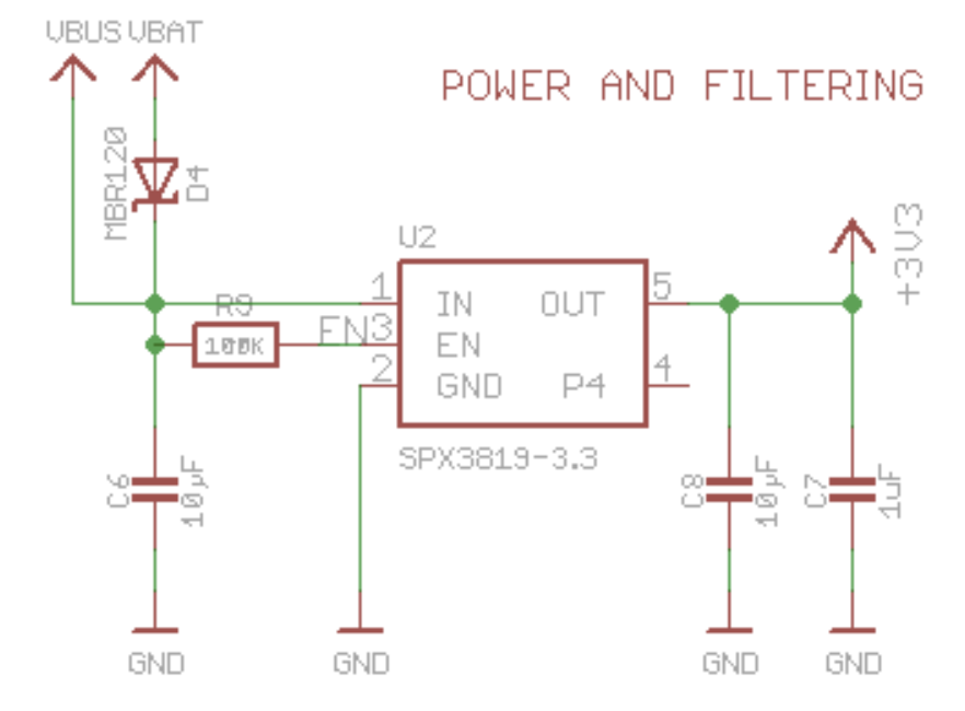
Original schematic: Original

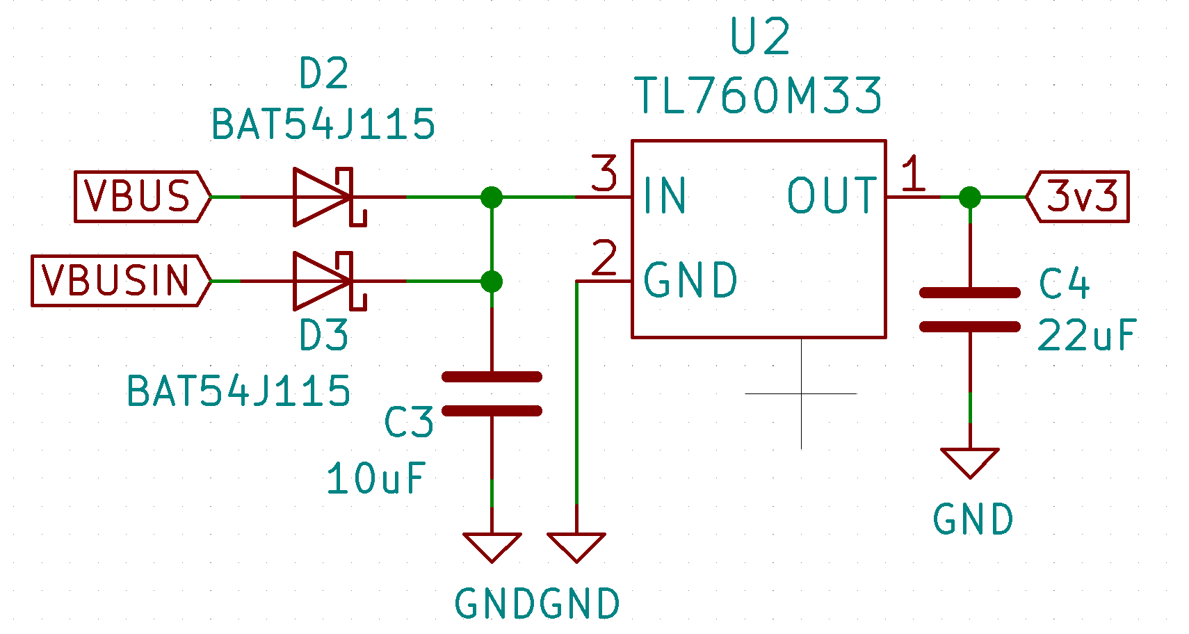
Replacement schematic: Replacement

\$\endgroup\$
9
  • \$\begingroup\$ Power dissipation in your regulator is (Vin-Vout)*Current so the answer will depend on how much output current is required. \$\endgroup\$
    – bobflux
    Commented Jan 6, 2020 at 10:38
  • \$\begingroup\$ How much current do you need from the regulator output? Have you calculated power dissipation in that case so the regulator does not overheat and melt? \$\endgroup\$
    – Justme
    Commented Jan 6, 2020 at 10:41
  • \$\begingroup\$ @peufeu that's a fair question, I've picked said TI regulator as it can output at max 500 mA, my circuit draws between 100-200 mA depending on the workload. One thing I seen online is recommendation to use mini-heatsinks for those TO-252 (or is it DPAC2) packages. I may consider adding one if needed though. \$\endgroup\$ Commented Jan 6, 2020 at 10:41
  • \$\begingroup\$ It definitely would not draw more than 300 mA at any circumstances. \$\endgroup\$ Commented Jan 6, 2020 at 10:44
  • \$\begingroup\$ So at the worst case scenario (max 20 V and 300 mA) there would be about 5W of power dissipation. I can't seem to find any numerical reference as at what level will my regulator need a heatsink. However this regulator has a large die pad on the bottom that I already imagine is made for heat dissipation. \$\endgroup\$ Commented Jan 6, 2020 at 10:50

1 Answer 1

2
\$\begingroup\$

The data sheet value for the thermal resistance between junction and "ambient" (when the tab is soldered to a 15 mm x 16 mm copper area of 1 oz/sq foot thickness) is 55 °C per watt of power dissipated: -

enter image description here

If you supply 20 volts to the regulator and it drops 16.7 volts in the process of producing 3.3 volts at the output, AND the output current is 300 mA, the power dissipated is about 4.9 watts.

This means that the device's "junction" (when mounted as per above) will heat up 55 x 4.9 °C above ambient i.e., in an ambient of 25 °C the junction will warm to 295 °C and this is clearly too much. You should also note that the local ambient will rise significantly above the average ambient under heavy dissipation situations.

So, you need either: -

  • A much bigger heat-sink area and/or thicker copper
  • A lower maximum continuous load current
  • A lower maximum ambient temperature
  • A fan targeted at the device
  • A switching regulator
  • A prayer
\$\endgroup\$
6
  • \$\begingroup\$ Thanks. That’s a great point. I might better look at alternatives to this then as the device is meant for a plastic enclosure and there won’t be much space for bigger heat sink nor for the active cooling. What could be an alternative to this? Are there miniature enough switching regulators? \$\endgroup\$ Commented Jan 6, 2020 at 11:59
  • \$\begingroup\$ No switching regulator circuit is usually smaller than an equivalent linear regulator due to the inductor needed but also, it might be that you keep the original linear regulator and use a switcher to deliver 5 volts from 20 volts. Maybe look at an LT1934 from linear tech/ADI or an LT8606 from the same. \$\endgroup\$
    – Andy aka
    Commented Jan 6, 2020 at 12:13
  • \$\begingroup\$ Forgive my lack of knowledge on this subject. But then why not just use switching regulator? From the first look something like Diodes Inc AP1509-33SG-13 or even LT1765EFE-3.3 from linear should be sufficient to provide (more than enough) power in a wide range of 5-20V that USB-C can carry. \$\endgroup\$ Commented Jan 6, 2020 at 12:19
  • \$\begingroup\$ If you are not concerned with the extra ripple voltage produced by a switcher then that's fine. The LT1765EFE-3.3 is a bit larger than the ones I specified. One man's "won’t be much space" is another man's "aint nowhere to put anything"! \$\endgroup\$
    – Andy aka
    Commented Jan 6, 2020 at 12:22
  • \$\begingroup\$ Thanks again for your suggestions, I made this imgur.com/a/xm8e9Da and it works like a charm staying pretty low on temperature too. \$\endgroup\$ Commented Jan 19, 2020 at 6:51

Your Answer

By clicking “Post Your Answer”, you agree to our terms of service and acknowledge you have read our privacy policy.

Not the answer you're looking for? Browse other questions tagged or ask your own question.