3
\$\begingroup\$

My project includes an ESP8266 (runs at 3.3v) and a USB C-Serial breakout. The USB module can optionally run at either 5v or 3v, and there's are solderable jumper pads to make that switch.
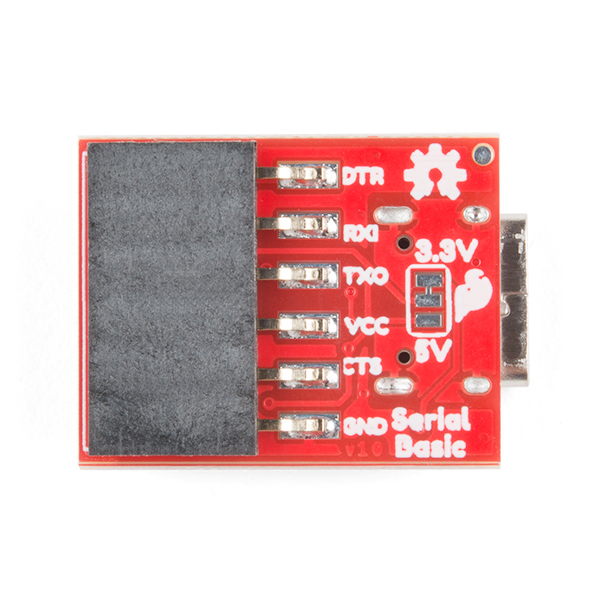
Here's where it gets tricky. While the ESP8266 requires 3v, I also have a separate battery charging module that requires 5v in to charge. So I have two obvious options:

  1. Set the USB to 5v mode. That requires the power to the ESP8266 use a voltage regulator, and it needs a logic level converter for the serial connection. That's two extra discrete components that can cost about $5
  2. Keep the USB at 3v mode. The ESP8266 will have no trouble talking to the USB module, but I'll need a 5v step-up converter to charge the battery, which will also cost about $5.

However, a third less orthodox idea comes to mind. Is there a way to "steal" 5v from the USB module (even while it's in 3v mode) by soldering a wire to the jumper pad in the middle? Maybe it would also require a resistor so it doesn't drain all of the power? Ideas on any of these 3 possible solutions are welcome, I'm entirely new to prototyping electronics.

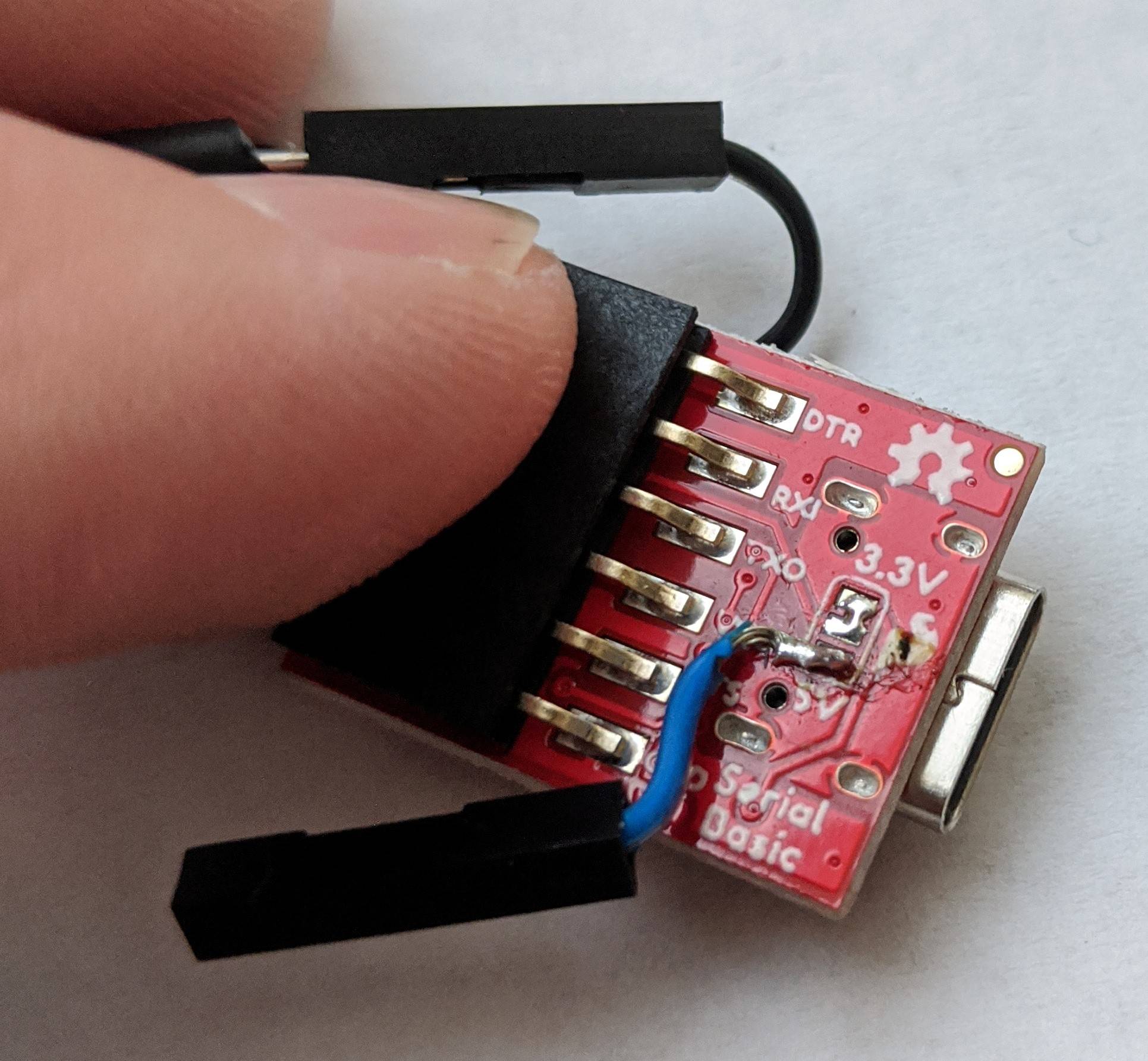
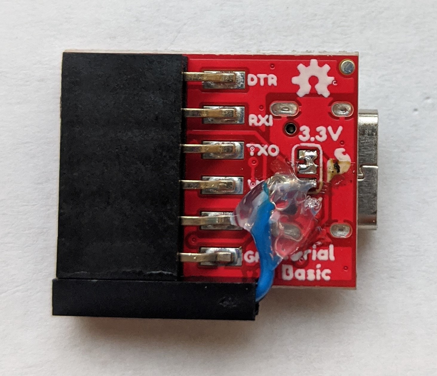
Edit: I did it! Here's a picture of the final product:

terminal soldered to pad terminal glued in place and solder protected with hotmelt

\$\endgroup\$
3
  • 3
    \$\begingroup\$ shouldn't you be soldering the wire to the bottom voltage selection pad, not the middle pad? \$\endgroup\$
    – jsotola
    Commented Jan 12, 2020 at 21:53
  • 1
    \$\begingroup\$ Yes, you would need to take the 5V from the bottom pad (the 5V one) not the middle pad. The middle pad will be whatever the selection is. \$\endgroup\$
    – Ron Beyer
    Commented Jan 12, 2020 at 22:08
  • \$\begingroup\$ I assumed the electricity was flowing in the other direction, but that does make more sense. \$\endgroup\$
    – Jonah
    Commented Jan 12, 2020 at 22:34

1 Answer 1

4
\$\begingroup\$

I don't know who designed that board, but it has several questionable connections.

First, CH340C chip datasheet requires V3 pin connected to VCC if VCC is 3.3V. On the board it is permanently connected to decoupling capacitor, which corresponds to 5V configuration.

On the other hand, the LEDs are connected to 3.3V supply, so they will (maybe) operate in strange mode when the logic levels are 5V.

So basically, the schematics is wrong whether it is configured for 3.3V or 5V power.

I'd recommend leaving the jumper at 3.3V and soldering a wire to the other (5V) pad of the jumper to bring 5V VBUS out of it.

UPDATE:

  1. Set the USB to 5v mode. That requires the power to the ESP8266 use a voltage regulator...

I realized that the statement above bothered me before. You seem to be under impression that you don't need voltage regulator if USB breakout is set to 3.3V.

However if you power ESP8266 from lithium battery you MUST HAVE voltage regulator between the battery and ESP anyway. Fully charged LiPo can go up to 4.2V, way above 3.6V maxium for ESP.

Also note, that VCC on the USB breakout is an output, not input. It will put out 3.3V when jumper is set to 3.3, but you cannot use it to power ESP, because there is no way to connect battery to the input of on-board AP2112 voltage regulator. Too bad, as it can supply up to 600mA, plenty for both ESP and CH340C.

Well... technically there is a way. You can cut a trace between VBUS of USB jack and input of AP2112, taking care to leave C1 on regulator side and C5 on VBUS side. Then you can solder another wire to "IN" pin of AP2112 and connect it to battery output. Then power ESP from 3.3V VCC output.

So, if you feel adventurous, you can download Eagle files from SparkFun and figure out how to mod the USB breakout. Otherwise you need additional 3.3V regulator between LiPo and ESP.

\$\endgroup\$
3
  • \$\begingroup\$ Wow thanks for the very thorough analysis. And thank you for the verification of my theory. So I don't need anything extra, I can just plug it right into the VCC pin on my battery charging module? \$\endgroup\$
    – Jonah
    Commented Jan 12, 2020 at 22:37
  • 1
    \$\begingroup\$ Yes, you can connect that 5V wire from jumper pad directly to 5V input of the charging module \$\endgroup\$
    – Maple
    Commented Jan 12, 2020 at 22:41
  • \$\begingroup\$ Thanks again for the help, I added an image of the final product to the question. \$\endgroup\$
    – Jonah
    Commented Mar 15, 2020 at 20:36

Your Answer

By clicking “Post Your Answer”, you agree to our terms of service and acknowledge you have read our privacy policy.

Not the answer you're looking for? Browse other questions tagged or ask your own question.