0
\$\begingroup\$

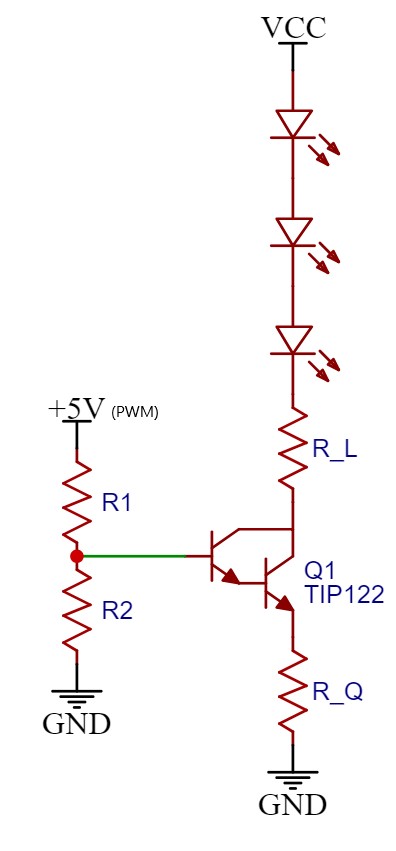
I'm trying to design a dimmable LED circuit board. It's controlled by an Arduino with its PWM signals. I'm new to electronics so I have some question regarding my design and knowledge on it. I've attached two diagrams I've made to help with the visualization. Vcc is 24 VDC and the 5 V is the PWM pin from the Arduino.

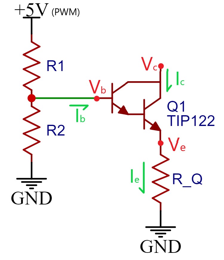
The idea is to control the RGB LEDs (1 W per channel) using a TIP122 Darlington transistor. From what I know, there is about a 1.4 V drop from the base to the emitter in the TIP122 (Vb-Ve = 1.4 V). The voltage at the collector and base should be the same (Vc = Vb). The base voltage is the voltage out of the voltage divider (R1 and R2). If R1 is equal to R2 (R1 = R2), then Vb should be half of 5 V or 2.5 V (Vb = 2.5 V). From that, the emitter voltage is 1.1 V (Ve = Vb - 1.4 V = 1.1 V).

The emitter current is the summation of the base current and collector current. However, the base current is super small compared to the collector's current so we can assume the emitter current is the same as the collector current (Ie = Ic). By changing the value of resistor (R_Q) after the TIP122, we can control the current flowing through the circuit (Ie = Ve/R_Q = 1.1 V/R_Q). This is assuming that the current gain is not larger than 1000.

From beginner LED circuits, I’m supposed to put a resistor (R_L) in series with the LED(s) to limit the current flowing through the LED and prevent the LED from being destroyed. But if the resistor after the TIP122 will limit the current, do I still need the R_L resistor?

As an example, let’s use the circuit in the second diagram. The usable voltage that can power the LED would be the difference between the supply voltage and the voltage at the TIP122 collector (Vcc-Vc = 24V-2.5V = 21.5V). Let’s assume the 3 LEDs in series each have a forward voltage of 6 V (Vf = 6 V) and a forward current of 750 mA (If = 750 mA), so there is 18 V of total forward voltage and 3.5 V left over (21.5 V – 3*6 V = 3.5 V). Now normally, we’d put a 4.67 Ω resistor (R_L = 3.5 V/750 mA = 4.67 Ω) to keep the current flowing through the LEDs at 750 mA. But with the TIP122 and R_Q, is the R_L still necessary? If R_L is not needed, would that still be true even when the leftover voltage is a lot larger? So say two LEDs in series instead of three giving a leftover 9.5 V instead.

If anything I said is false, please let me know. I’m just explaining my thought process in my design and would appreciate any feedback on it.

enter image description here

enter image description here

\$\endgroup\$
8
  • \$\begingroup\$ Things to think about: what is your PWM speed and can the darlington switch that fast? If I were to do something along these lines, I'd pick a N channel mosfet. They can switch faster than a darlington and are easier to drive and you will have less losses. \$\endgroup\$
    – Aaron
    Commented Jan 13, 2020 at 21:12
  • \$\begingroup\$ @Aaron If it's coming from a typical Arduino then the PWM frequency will be less than 1kHz. \$\endgroup\$ Commented Jan 13, 2020 at 21:14
  • \$\begingroup\$ I'm using an Arduino Micro and their website said it has a pwm frequency of 490Hz. I've used it with a Darlington before on a test circuit and it worked fine to me. There might be some tiny flickering if I giving it a blow 10% duty cycle but it's not very noticeable. \$\endgroup\$
    – Agriculex
    Commented Jan 13, 2020 at 21:44
  • \$\begingroup\$ @Agriculex What purpose is served by the PWM'd light from R, G, and B LEDs? What's the end goal? (It matters in selecting from among a variety of things I might say.) \$\endgroup\$
    – jonk
    Commented Jan 13, 2020 at 22:19
  • 1
    \$\begingroup\$ @WhatRoughBeast, Huh strange, I thought 5V was fine for driving NFETs, but what do I know? FETs. \$\endgroup\$
    – Aaron
    Commented Sep 26, 2022 at 22:45

1 Answer 1

1
\$\begingroup\$

Without \$R_L\$, a much larger voltage may appear across the transistor, from collector to emitter. It is incorrect to say that the voltage at the collector is the same as the voltage at the base. The voltage at the collector will change as needed to control the current.

If the base voltage is about 2.5V then the emitter voltage will be about 1.1V. If the LEDs drop 6V altogether then the remaining voltage, \$24 - 6 - 1.1 = 16.9\text{V}\$ will appear from collector to emitter of the transistor. If 750mA is flowing through the LEDs then that much current is also flowing through the transistor, and it will be dissipating about 12.7W of power. You will need a sizeable heat sink to keep it from burning up.

There is no free lunch here. If your power supply is 24V and only 6V is across the LEDs at 750mA, then you will be wasting 13.5W somewhere. You can add a high-power resistor in series with the LEDs to reduce the power consumed by the transistor, but you are wasting 75% of your power no matter what.

\$\endgroup\$
1
  • 1
    \$\begingroup\$ That's insightful to know. I did notice the transistor getting a lot hotter on the red channel compared to transistor for the blue & green channel in the 3in1 RGB LED. Red does have a smaller forward voltage too. \$\endgroup\$
    – Agriculex
    Commented Jan 13, 2020 at 21:40

Your Answer

By clicking “Post Your Answer”, you agree to our terms of service and acknowledge you have read our privacy policy.

Not the answer you're looking for? Browse other questions tagged or ask your own question.