2
\$\begingroup\$

I have a differential manchester encoded 0 to 5v data stream at 62500bps. What hardware do I need to get this into something I can work with, ie arduino, pi, etc?

I have searched for chips/eval boards on digikey and can't find anything that can decode differential manchester.

I have hooked it up to an arduino uart, but it is doing 8-N-1 on something that I need to see all the bits. It's is also decoding it improperly (of course). I have thought of sampling at double the baud rate and trying to do something with a lookup table, but this seems awfully hackish.

Below shows my thought process and the logic analyzer is giving me enough information to analyze the protocol, but now I need to turn it into something I can process in real-time.

Requirements: Error free to five 9's, some errors will be known because packets have a checksum. One off solution.


Other Possible Relevant Information:

A continuation of this question regarding an unknown serial bitstream.
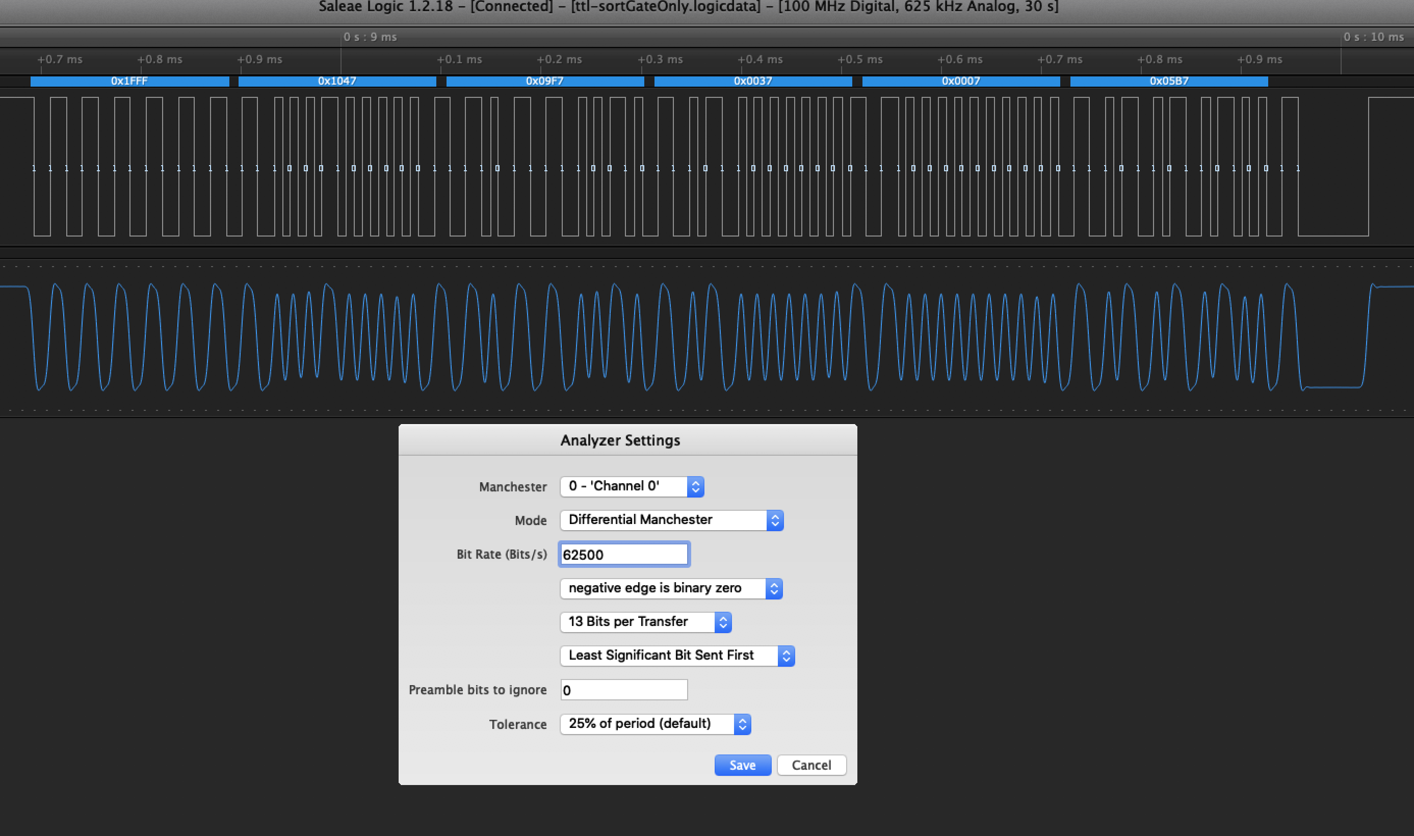
Valid Packet This picture shows a typical packet of the DeLaval Alcom bus.

We are grabbing 13 bits at time and ignoring the first and last nibble.

Thus the packet is: FF 04 9F 03 00 5B.
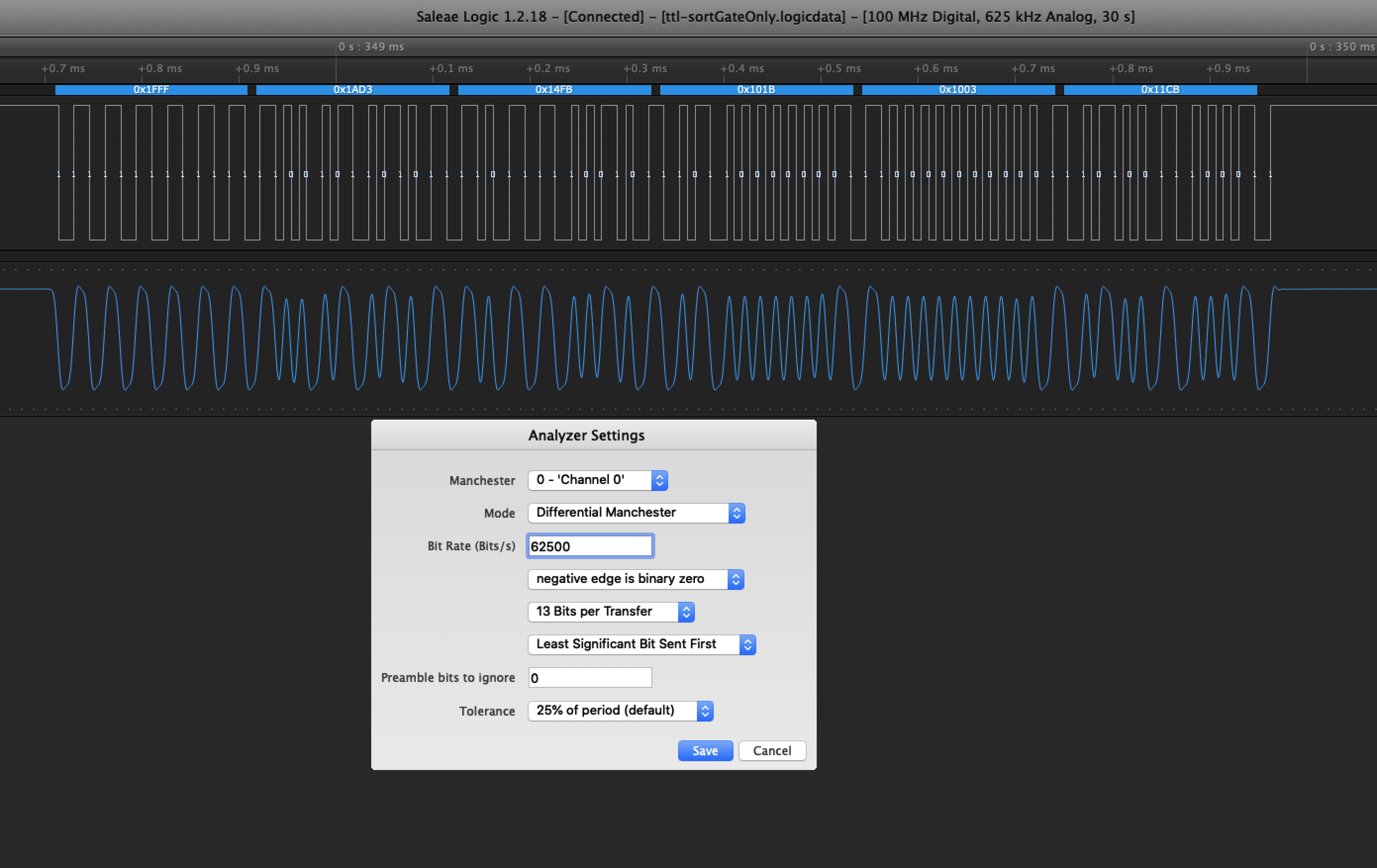
Skewed Packet This packet we cannot read correctly with 13 bits. We have a bit skew because the number of start bits are different as compared to the previous packet. This can be fixed in software.

  • Packet #1 - This packet checks if MPC (or any node) is alive
  • FF 54 9F 03 00 43
  • FF Start  54 To node 84, this node is an Alpro MPC.
  • 9F Packet type 
  • 03 From node Alpro master
  • 00 Data
  • 43 calculated checksum (not sure how yet, 2 Byte CRC 16?)

These are "are your alive" packets. They are sent and don't wait for response. Response comes later if node is alive.

  • Sample of packets 
  • FF 55 9F 03 00 F6
  • FF 56 9F 03 00 B2 <- saw this same packet twice with the same checksum
  • FF 5C 9F 03 00 B1
  • FF 5D 9F 03 00 04
  • FF 04 9F 03 00 5B
  • FF 0F 9F 03 00 ED <- node 15 does not exist. maybe checking that it is there or not?
  • FF 58 9F 03 00 C8
  • FF 59 9F 03 00 7D
  • FF 5A 9F 03 00 39
  • Packet #2 - This packet is from the alpro master saying what to show on the screen of the sort gate MPC: 1463.

  • FF 3D 0D 03 1B 17 B7 05 01 00 00 00 00 00 00 00 00 D5

  • FF Start
  • 3D to node 61, sort gate controller
  • 0D Packet type
  • 03 From node, alpro master
  • 1B 17 Data of 6935 means nothing to me.
  • B7 05  Data 1463 16 bit little endian, which matches the cow we used.
  • 01 00 00 00 00  00 00 00 00 Data, no idea
  • D5 calculated checksum.

FF start is not really FF. It's a string of 1's of somewhat variable length.

\$\endgroup\$
6
  • \$\begingroup\$ You can use a 16x clock and sync edges to mid-bit edge only @ 1MHz or use non-retriggerable 1 shot of 3/4T = 12.0 us and make recovered clock from data. then test with PRSG what kind of performance do you need? define max jitter and BER \$\endgroup\$
    – D.A.S.
    Commented Jan 16, 2020 at 22:39
  • \$\begingroup\$ Apart from the other suggestions, you could get a CPLD evaluation board where it should be pretty simple to make it operate as a translator. (I found one that costs £12:50 for a single unit based on the XC9572). \$\endgroup\$ Commented Jan 17, 2020 at 13:36
  • \$\begingroup\$ @TonyStewartSunnyskyguyEE75 What exactly is "3/4 one shot"? I'm having a hard time googling that. \$\endgroup\$
    – Navin
    Commented Feb 14, 2020 at 5:12
  • \$\begingroup\$ Did I not say 3/4T?, T is the bit period \$\endgroup\$
    – D.A.S.
    Commented Feb 14, 2020 at 11:16
  • \$\begingroup\$ It’s a delay timer to sample Biphase and convert to NRZ \$\endgroup\$
    – D.A.S.
    Commented Feb 14, 2020 at 11:25

2 Answers 2

3
\$\begingroup\$

Well it can't be received with an UART easily. One thing you could do with Arduino is to feed the data to Timer Capture Input pin and triggering on the edges and every time an edge happens make it trigger on the other edge and look at timer value how much time was between edges to decode the bits.

\$\endgroup\$
3
  • \$\begingroup\$ It is trivial to make a Manchester decoder from simple logic and 3/4 1shot. then you can use Arduino to do real work \$\endgroup\$
    – D.A.S.
    Commented Jan 16, 2020 at 22:35
  • 1
    \$\begingroup\$ I took a look at timers and interrupts on an arduino. My smallest transitions are ~8μs on the bitstream, with the rest being ~16μs. This is too fast for the arduino, it takes about 18μs just to do the simplest. For a slower bitstream your method would probably work. \$\endgroup\$ Commented Jan 17, 2020 at 18:46
  • 1
    \$\begingroup\$ I see; some assembly might be required. One other trick could be to just trigger on the first falling edge, and sit in a counting loop until bit changes, and store counter variable or timer count to an array until no more changes arrive, and decode the array later. Or just read state and store to array loop until array is full. Or connect data to SPI data input and sample the bitstream. \$\endgroup\$
    – Justme
    Commented Jan 17, 2020 at 19:22
1
\$\begingroup\$

In addition to what Justme recommended: at 62.5 kbd, you can just probe the input pin at say 145 kSamples/s and do all the de-manchestering by converting the samples to +/- 1 and then multiplying consecutively.

Timing offset, rate error and sync loss nonwithstanding, of course.

On faster processors, just sufficiently oversample the pin (say, at 500 kS/s), and then throw classical signal processing at it for clock recovery, and then decimate and de-manchester in software.

\$\endgroup\$

Not the answer you're looking for? Browse other questions tagged or ask your own question.