3
\$\begingroup\$

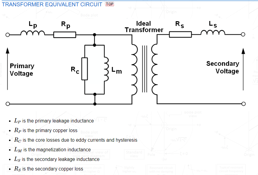
enter image description hereIn equivalent circuit of a transformer, there are two inductances, \$L_p\$ and \$L_s\$. These are called Leakage inductances, as the name suggests due to the leakage flux from both the coils.

1) Are these self inductance? Cause, when we calculate the voltage across an inductor we include two components, one is due to self induction, \$-L \frac{di}{dt}\$ and the other due to mutual \$M \frac{di}{dt}\$. Are \$L_p\$ and \$L_s\$ only due to leakage flux or they generally represent self inductances of both the coils? If yes, what about the rest of the flux, won't that induce emf?

2) In the book I'm following,

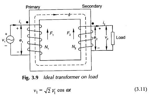
In an ideal transformer, assuming there's no leakage of flux, the induced emf in the primary coil will be given by $$e_1 = \dfrac{d\lambda_1}{dt} = N_1\dfrac{d\phi}{dt}$$ and for an ideal transformer $$v_1=e_1$$and thus \$e_1\$ and therefore \$\phi_1\$ must be sinusoidal of frequency \$f\$ Hz, the same as that of the voltage source. So, $$\phi = \phi_{max} \sin\omega t \implies e_1=N_1\dfrac{d\phi}{dt}=N_1\omega\phi_{max} \cos\omega t$$ Therefore, induced emf leads the flux by \$90^\circ\$

How can the induced emf lead the flux by \$90^\circ\$? An induced emf is created only when there's a change in the flux, which is produced only when there's a current flow, which means the flux has to be produced first to create an induced emf.

3) Why does resistor reduce the lag in a RL circuit? I understand why current lags by 90° with the voltage across the inductor. (After watching this) But I don't understand why that lag, would be diminished by the presence of a resistor, the resistor would just decrease the amplitude of the current. I thought that, there would be lesser voltage across the inductor in a RL circuit, as some would fall across the R, and hence the change would also be less which produces smaller opposition. But then if I apply that reduced voltage across L alone in a separate circuit, there's a solid 90° lag, it's not reduced. If there were a capacitor, it would push the current more, and therefore it would reduce the lag, by why does the resistor reduce the lag in a RL circuit?

\$\endgroup\$

3 Answers 3

2
\$\begingroup\$

Are Lp and Ls only due to leakage flux or they generally represent self inductances of both the coils? If yes, what about the rest of the flux, won't that induce emf?

Lp and Ls are leakage inductances due to imperfect coupling between the primary and secondary. Lm is the prime mover when it comes to flux because it is the magnetization inductance: -

enter image description here

Above image from here.

How can the induced emf leads the flux by 90∘

The current in Lm is 90∘ lagging the primary voltage because

$$V_{primary} = L\dfrac{di}{dt}$$

Current and magnetic flux (\$\Phi\$) are in phase but, there is a further 90∘ shift in the induced secondary voltage due to: -

$$V_{secondary} = N\dfrac{d\Phi}{dt}$$

Why does resistor reduce the lag in a RL circuit?
For a very high frequency stimulus the inductor would be seen as open circuit compared to R hence, as frequency rises, the 90∘ lag gets smaller.

\$\endgroup\$
14
  • \$\begingroup\$ Thank you for answering, so is Lm the self-inductance of primary coil? then what about secondary coil's self-inductance? \$\endgroup\$ Commented Jan 30, 2020 at 10:07
  • \$\begingroup\$ Yes Lm is (apart from leakage) and, it 100% couples to the secondary coil but don't forget the leakage inductance Ls because that doesn't couple. So if Lm is 1 henry and turns ratio is 10:1, the equivalent secondary inductance (if it could be disentangled from the primary mag inductance) would be 10 mH. \$\endgroup\$
    – Andy aka
    Commented Jan 30, 2020 at 10:15
  • \$\begingroup\$ For the second question, sorry I don't understand it intuitively. The voltage across an inductor is proportional to the change in current because \$\epsilon= \dfrac{d\phi}{dt}\$ and \$\phi=Li\$. So doesn't it fundamentally depend on the change in flux and hence current? The current increases(changes) the maximum while starting in a sine wave, which means the flux changes the maximum so the voltage is at the maximum, but there flux had to be present before the induced voltage, doesn't it? \$\endgroup\$ Commented Jan 30, 2020 at 10:15
  • \$\begingroup\$ Please bare with me here, very sorry if you had already answered this question, how did you say that the secondary inductance would be 10mH. Ls is that inductance which induces a voltage due to the leakage flux only right? Is Ls the secondary coil's self-inductance? \$\endgroup\$ Commented Jan 30, 2020 at 10:21
  • \$\begingroup\$ It's 10 mH because impedances reflected from one side to the other are modified by turns ratio squared. For your previous comment I don't understand what you are trying to say. \$\endgroup\$
    – Andy aka
    Commented Jan 30, 2020 at 10:23
1
\$\begingroup\$

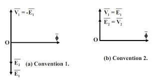
Many books Induced emf as lagging and many of them show it as leading. The choice being the result of convention selected. enter image description here
Source: https://www.eeeguide.com/ideal-transformer-on-load/

Faraday's law says :

e1 = NdΦdt.

Paired with Lenz's law it says:

e1 = - NdΦdt

So in the book that you are following, they would have marked the polarities of induced emf according to Lenz's law and then simply applied Faraday's law to say induced emf leads the flux.

The applied voltage that induces the flux, leads the flux by 90 and the emf opposing the voltage applied (Lenz's law) caused by flux, lags the flux by 90 and applied voltage by 180. Shown by the following phasor.

enter image description here
Source: http://ecoursesonline.iasri.res.in/mod/page/view.php?id=2535

In convention 1, phasors E1 and E2 are drawn 180° out of phase with respect to V1 in order to convey that the respective power flow directions of these two are opposite. The second convention results from the fact that the quantities v1(t), e1(t) and e2(t) vary in unison then why not show them as co-phasal and keep remember the power flow business in one’s mind.

One convention takes in account the physical aspects of transformer action ie lenz's law while other convention just deals with the circuit analysis without giving any physical insight on the phenomenon.

\$\endgroup\$
0
\$\begingroup\$

Lp and Ls

They are taken to the equivalent circuit to present the fact that primary and secondary have only partially common flux. A part of the flux that primary generates bypasses the secondary and vice versa. Lp and Ls present that part of the total winding inductances that are useless for the transformer operation.

90 degrees phase lag

Maximum induced voltage doesn't need maximum flux, it occurs when the flux changes fastest. The fastest flux change occurs in sinusoidal flux at zero crossing. BTW. Flux generated by a coil is equal with Inductance x coil current.

Why series resistor reduces the phase lag of current in LR series circuit

The current in both L and R is the same, they have the same phase angle. To make thinking simpler set the phase angle of the common current = 0. The voltage of the resistor has also phase angle = 0. The voltage of the inductor has phase angle =+90 degrees (=90 degrees lead to current).

The total voltage of the LR series circuit is shown by the vector sum of the phasors of the R and L voltages. It has phase angle somewhere between 0 and +90 degrees. The angle decreases as the 0 degrees resistor voltage increases

enter image description here

In the right the current is the same as in the right, but the total voltage over the LR circuit must be bigger because the resistance is bigger. The phasor diagram shows that the difference between the phase angles of the total voltage and the current has decreased.

I must admit that this drawing proves nothing if you do not know how phasors and sinusoidal currents and voltages with same frequency are related. Proving the result without phasors in pure time domain is possible only with differential equations. That's because the time domain voltage vs current law for the inductor is a differential equation.

\$\endgroup\$
2
  • \$\begingroup\$ "The current in both L and R is the same, they have the same phase angle" Oh so the phase difference is only in the voltages? I've got another doubt regarding transformers, if the magnetization current is what produces the magnetic flux and we have modeled it with Lm, what's happening in the remaining "ideal" transformer, what current flows in the primary? \$\endgroup\$ Commented Jan 30, 2020 at 12:39
  • \$\begingroup\$ In ideal transformer the flux caused by primary current is exactly compensated to zero by the flux caused by the secondary current. If there's no secondary current, there's also no primary current. In Ideal transformer Lm is infinite. Finite Lm in the equivalent circuit is inserted to consume the idle current of real transformers which is caused by finite primary inductance. \$\endgroup\$
    – user136077
    Commented Jan 30, 2020 at 13:33

Your Answer

By clicking “Post Your Answer”, you agree to our terms of service and acknowledge you have read our privacy policy.

Not the answer you're looking for? Browse other questions tagged or ask your own question.