0
\$\begingroup\$

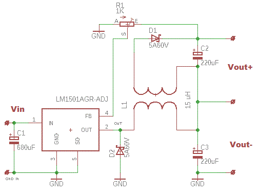
I'm trying to build a DC-DC split-rail converter using circuit from this article. My goal is to split 12..14V input voltage into +2.4V and -2.4V. To do that, I choosed LM1501AGR-ADJ IC, calculated the needed inductance value (15 uH) and made the coupled inductor, then built the following circuit:

enter image description here

It works OK, but only when I apply a certain load. When the load is 1K or more, Vout- is about -11V, and Vout+ is -0.2V (input voltage is 12V). Load resistance of 220R or less makes Vout- equal to -2.39V, and Vout+ to 2.36V, which is just fine for my purposes.

I don't like the fact that circuit needs some "dummy" load to work correctly, because it means aditional power consumption. I'm gonna use battery as the power supply, so I whant it to consume as less power as possible. Besides, it looks like a very quick'n'dirty solution. Are there better ways to solve this problem?

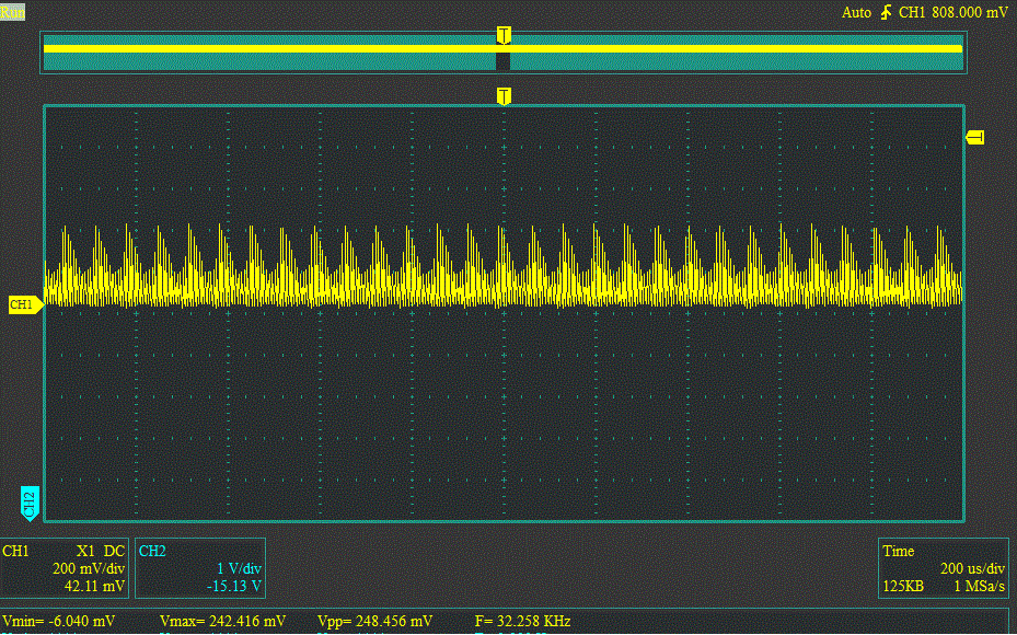
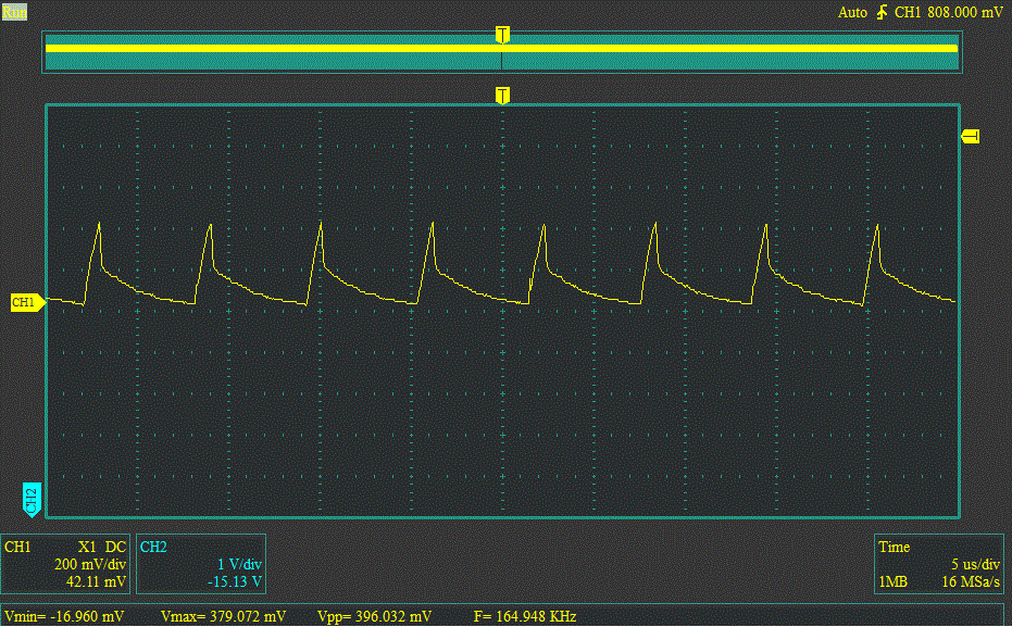
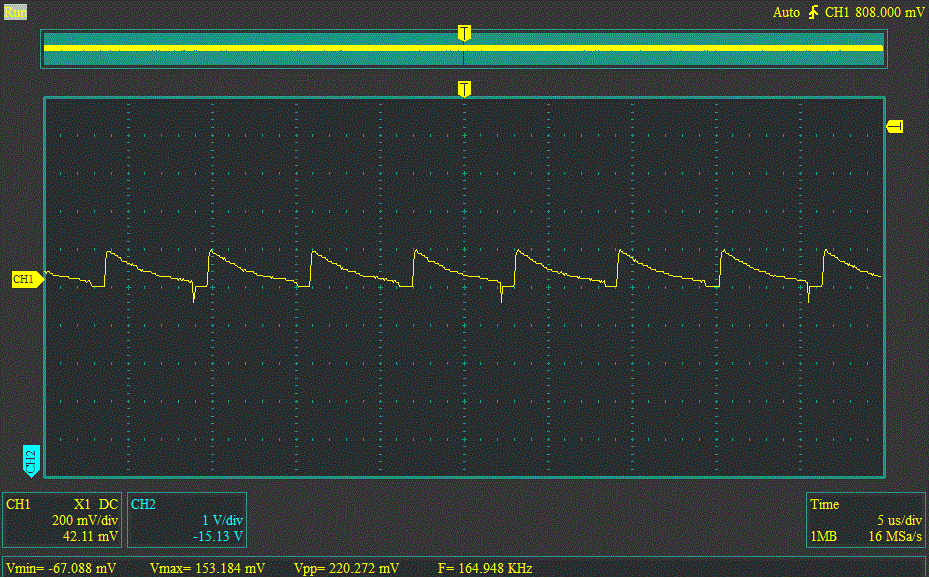
To provide some additional information about the circuit, I tried to obtain the inductor's currents waveforms. To do that, I removed C2 and C3 and applied the load resistors 10R, than measured the voltage waveform on them. Here is what I got:

Primary coil

Primary coil

Primary coil - large scale

Primary coil - large scale

Secondary coil

Secondary coil

By primary coil I mean the coil which is connected directly to IC.

\$\endgroup\$
9
  • \$\begingroup\$ Did you respect the dot notation on the coupled inductor in your design? \$\endgroup\$
    – Andy aka
    Commented Feb 2, 2020 at 17:39
  • \$\begingroup\$ What Andy said, and for a "flybuck" design like this you'll need enough load on the primary output to be sure the inductor has enough energy to supply the secondary output. (This is a non-synchronous converter.) You might want to check this out: ti.com/power-management/… \$\endgroup\$
    – John D
    Commented Feb 2, 2020 at 18:17
  • \$\begingroup\$ @Andy aka, yes, I did. \$\endgroup\$
    – msmirnov91
    Commented Feb 2, 2020 at 22:16
  • \$\begingroup\$ @John D, I'll try to apply some load as soon as possible and write back - maybe this will help. \$\endgroup\$
    – msmirnov91
    Commented Feb 2, 2020 at 22:21
  • \$\begingroup\$ @John D I tried to add some load (1K resistors for both outputs) - unfortunately, it did not help... Maybe this diodes are not appropriate? \$\endgroup\$
    – msmirnov91
    Commented Feb 4, 2020 at 21:47

1 Answer 1

0
\$\begingroup\$

This answer is just to summarise up the John D's explanations. The "primary coil" (which is connected directly to IC) must reserve enough energy for the "secondary coil". Since the inductor current is discontinious, it is possible only when the load consuming enough current is applied. Without it the circuit will not work correctly - in my case the output voltages without load were completey different from expected values. So, dummy load in my case is necessary. The other way is to use the circuit with continious current mode.

\$\endgroup\$

Your Answer

By clicking “Post Your Answer”, you agree to our terms of service and acknowledge you have read our privacy policy.

Not the answer you're looking for? Browse other questions tagged or ask your own question.