0
\$\begingroup\$

I have two Arduinos: Mega and Nano, and 2 steel pieces of wire as antennas which I stuck directly in the pin slots.

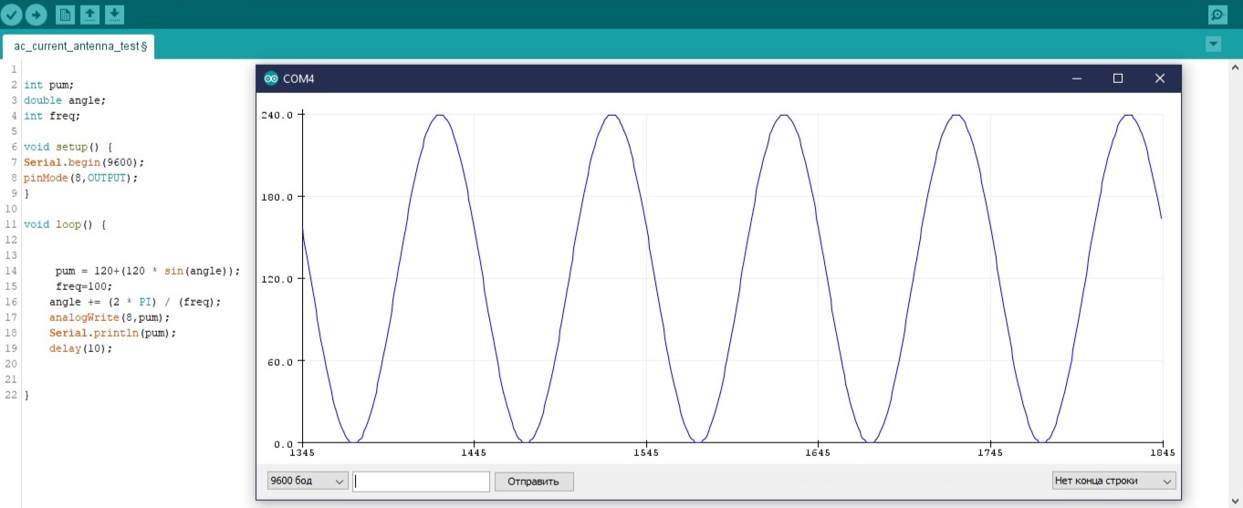
I've setup my Mega2560 to generate an alternating current on one of its pind (PWM digital pin 8) so now I have a sinusoidal signal (0-5v,40mA) as you can see in thid picture:

enter image description here

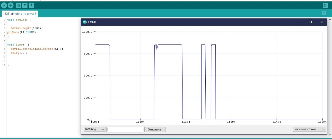
A second Arduino (Nano) I've setup as a receiver. I stuck a wire as an antenna in Analog Pin 1, and connected it with a pulldown 1k resistor, so there won't be any noise. You can see in a picture below AnalogRead function of this pin (I've touched the antenna a couple of times:)

enter image description here

How do I have this sine wave signal on my Arduino Nano (receiver A1 pin) via my antenna and electromagnetic waves in simplest way that possible?

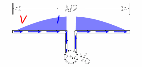
Should I use this dipole type of antenna instead of just a wire:

enter image description here enter image description here

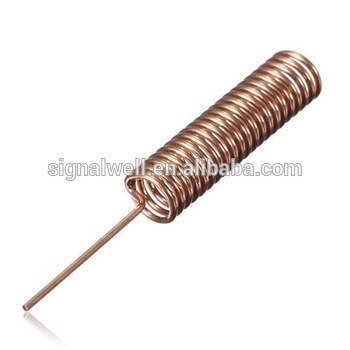
Or this coil type antenna? I've messed up, and can't find any examples of basics of EM waves working with Arduino, just an premade radio frequency modules.

p.s: Here is an interesting tutorial I found recently, but it only implements a "transceiver with a wire as an antenna" part of my question.

\$\endgroup\$
5
  • 2
    \$\begingroup\$ Well, that won't work. Still, you've discovered why all the examples you found use external radio modules. For an explanation of why it won't work could you let us know what frequency your program generates? \$\endgroup\$
    – Graham Nye
    Commented Feb 18, 2020 at 14:12
  • 1
    \$\begingroup\$ Assuming "freq = 100" means 100 Hz... here's an example of an antenna for 24000Hz, with a wavelength 240 times smaller than yours. It's over a mile across; you might need something a bit bigger. en.wikipedia.org/wiki/VLF_Transmitter_Cutler \$\endgroup\$
    – user16324
    Commented Feb 18, 2020 at 14:24
  • \$\begingroup\$ Note that the signal you are trying to receive normally counts as noise! If you do something "to make sure there won't be any noise" then it's also hurting your signal. \$\endgroup\$ Commented Feb 18, 2020 at 15:45
  • \$\begingroup\$ @graham-nye Since my code generates a 99 samples in one second plus 10 milliSecond delay, and the amplitude of a sine wave is something near 255 samples, it took near 4 seconds to get a one full oscillation, so the real frequency probably is 0.25 Hz \$\endgroup\$ Commented Feb 18, 2020 at 15:55
  • \$\begingroup\$ A dipole antenna would be much more efficient. Unfortunately for 0.25 Hz it will need to be nearly 600,000 km long. You'll need a second one for your receiver. For everything else I'll refer you to the answer by @dex. \$\endgroup\$
    – Graham Nye
    Commented Feb 18, 2020 at 18:22

1 Answer 1

3
\$\begingroup\$

The short answer is: you'll need at least a bit more circuitry to make this work. Depending on the end goal: buy a sender + receiver kit or revert to analog electronic cirtuits.

The long anwser:

First things first, since you use a vanila (meaning: using the arduino environment) arduino mega, the sample frequency of the PWM is set to 490Hz (arduino pwm frequencies), this could maximally result in a signal of 245Hz (Nyquist frequency). Which is right in the ELF frequencies.

This 245Hz corresponds to a wavelenght of about 1200km. Meaning that a half wave dipole would need to span about 600km ... I doubt this will fit on that breadboard. Of course nothing stops you from using smaller antennas, ones that are only fractions of the wavelength. But you'll also reduce the received energy by the antenna as you make it smaller. (ELF was and is still used in submarine communications, their solution to the energy problem is to use very long trailing wire antennas. This does not even go into the fact that at 490 Hz samplerate you would be making a square wave at 245Hz rather than a sine. But then with the selected 100Hz you have an even lower fequency!

Now, apart from the minimal capability for your antenna to pickup any energy, it has not been coupled in a controlled way. Impedance mismatches will make sure that most of the enery is not even radiated properly, and on the receiving side the same effect will further limit the reception.

And generally speaking the signals coming of an antenna are very weak at best, possibly in the microvolt range. And the arduino adc measures in the milivolt range. A factor of a 1000 times bigger. This explains why you would not see any received sine. To have anything useful you'd need to build a very sensitive ampifier stage that is filtering out all frequencies except your signal. The fact that you see the reaction on the output when you touch the antenna is because the human body is not a bad signal receiver, albeit not a very high performing antenna. (In terms of directionality or signal selectivity. I just picks up pretty much anything.)

Also know that designing antennas and their properties is almost as much an art as it is science! Nothing to feel bad about.

Just as a sidenote: I've done similar experiments years back. Just as a demonstration you can send out a pwm tone on a pin with a long wire as antenna. Next you can use a simple old analog radio to pickup the signal. If you give it some time and effort you'll be listening to the Mario theme played by and arduino through a radio.

So in conclusion and depending on your end goal:

  • If you want to set up a communication channel: buy a sender receiver kit of ebay and use it as a serial bridge.
  • If you want to learn about electromagnetic communication: go back to the basics and build a few basic circuits. (Pro tip: breadboard are pretty much the worst basis for such circuits due to parasitic influences!)
\$\endgroup\$
3
  • \$\begingroup\$ Thank you for such clear and full answer. I'm currently work on this transceiver tutorial link, so i got this idea if i can implement it with microcontrollers. Now somethings become more clear, and i will try to work on amplifying stages of my receiver side, and more propper radiation on transceiver side. Thanks again! \$\endgroup\$ Commented Feb 18, 2020 at 16:14
  • \$\begingroup\$ Maybe also look to drive the arduino pins at a lower level. Direct register access is orders of magnitude faster than analogWrite or digitalWrite! Combine this with some high Q bandpass filter and you'll get way higher frequencies. (In the order of a few MHz.) This is much easier to radiate, and pickup on. The filter should eleminate the harmonics of the square wave. Receiver should be tuneable, google is your friend! This could get you a very basic, low power, CW setup. (PS: happy to help with followup questions!) \$\endgroup\$
    – dex
    Commented Feb 18, 2020 at 22:08
  • 1
    \$\begingroup\$ here i found an tutorial close to my topic. you can use arduino to transmit an audio signal to 666kHz and i tested it and it works, so i think its defenetly not only the monophonic signal and i think that means that pwm can give more that 490hz output, so here is a link if you interested instructables.com/id/AM-Transmitter-With-Arduino \$\endgroup\$ Commented Apr 25, 2020 at 18:04

Your Answer

By clicking “Post Your Answer”, you agree to our terms of service and acknowledge you have read our privacy policy.

Not the answer you're looking for? Browse other questions tagged or ask your own question.