0
\$\begingroup\$

I want to design the following reverse protection circuit: Rev Polarity From Battery to SIM808 Chip
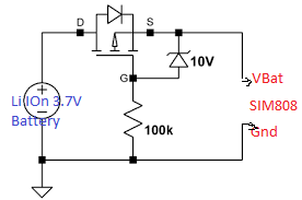
The gist of the design is that I want to run a SIM808 chip from a 3.7V battery. I understand that the circuit as such will protect if the user connects the battery the wrong way. But,

The Sim808 chip has a neat built in battery charger and one connects it as follows: SIM808
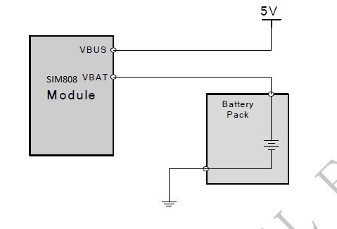
My question is this. Assuming the user connects the battery correctly will the mosfet above allow the SIM808 to charge the battery? Or will it block it?

\$\endgroup\$
2
  • \$\begingroup\$ you should show how the two will interface with each other, but if i get you right, it doesn't look like you will have an issue; from the "front" of the fet, you can still use the intrinsic diode. \$\endgroup\$
    – dandavis
    Commented Feb 25, 2020 at 19:03
  • \$\begingroup\$ Hi Dan, thanks a lot. If you look at the top pic. The VBAt line would go to the VBAt pin of the SIM808 as shown by the bottom pic. In other words the "Battery Pack" at the bottom would be replaced by the top pic. \$\endgroup\$ Commented Feb 25, 2020 at 19:57

1 Answer 1

0
\$\begingroup\$

If the battery is correctly placed, voltage between drain and gate will always be about 4V. Then voltage between source and gate will be about 4V - the diode forward voltage (about 1V). So MOSFET will be on, Vgs and Vgd will be the same and current could flow in both directions.

I would pay attention to the following : If your lithium-ion battery is too low, the Vgs voltage may not be enough to turn on the MOSFET fully. Current will be able to flow but in the worse case it will flow through the intrinsic diode causing voltage drop and power loss. In this particular case you won't be able to charge the battery (intrinsic diode will block the current). So check the threshold voltage that turn your p-Mos on to be sure that it fits with your battery voltage.

\$\endgroup\$
2
  • \$\begingroup\$ HI Mathieu. Thanks. That did cross my mind. But I am thinking of using a p-Mos with a low turn on voltage. Something like the DMP2110U-13 \$\endgroup\$ Commented Feb 25, 2020 at 20:07
  • \$\begingroup\$ I edited my answer. It does not change anything to the conclusion, but I misunderstood how the MOS worked. I swapped gate and source in my head ^^. That's Vgs voltage that makes the MOS on or OFF, not Vds as I previously mentioned. \$\endgroup\$
    – Mathieu G.
    Commented Feb 25, 2020 at 20:50

Your Answer

By clicking “Post Your Answer”, you agree to our terms of service and acknowledge you have read our privacy policy.

Not the answer you're looking for? Browse other questions tagged or ask your own question.