6
\$\begingroup\$

In reference to my question Arduino Controlled Power Supply for more details and a test program.

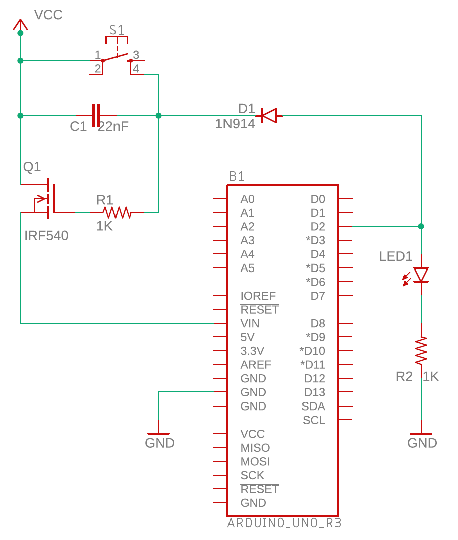
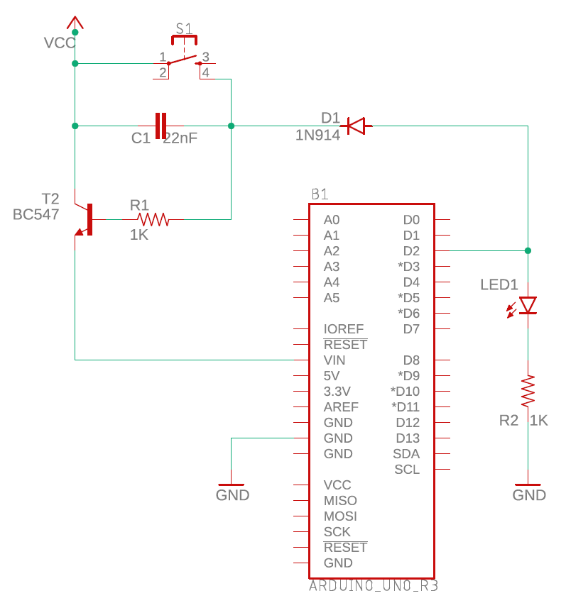
Why is it that my circuit involving a transistor does not work (see below) whereas a similar circuit using a MOSFET does work?

Also, why is it that when the power is cut in the transistor based circuit, the Arduino dies instantaneously, whereas in the MOSFET based circuit, the Arduino gradually fades away over a period of 3-4 seconds? When I say it "fades away", the LED's will dim over that 3-4 seconds. It is like there is some capacitance that keeps it going until the charge is exhausted - but this does not occur in the transistor based circuit.

The idea behind this circuit is to maximise the life of a 9V battery powering the Arduino. The idea is to allow an external physical event (pressing S1) to power up the Arduino. Then, the Arduino, via Pin D2, will keep the power on after S1 is released until such time as it has done what it needs to do. Finally the Arduino will drop Pin D2 to a low state to shut off the power.

Following are the two circuit diagrams.

Firstly the transistor based circuit - which does not work (the Arduino dies as soon as S1 is released - and it dies instantaneously).

Transistor based Arduino power management

Secondly, the MOSFET based circuit - which achieves the desired result, but the Arduino gradually "fades away" when D2 goes LOW. This is OK, but it would be nicer if the Arduino powered down much more quickly.

enter image description here

\$\endgroup\$
9
  • 12
    \$\begingroup\$ Did you know that the T in MOSFET stands for transistor? If you write "Bipolar transistor" or "NPN transistor" then the title makes more sense. \$\endgroup\$ Commented Mar 11, 2020 at 10:03
  • 12
    \$\begingroup\$ NEITHER CIRCUIT SHOULD WORK. The MOSFET cct appearing to work is a fluke. The turnoff is probably achieved by leakage through the diode. || In both cases base/gate drive SHOULD be higher than Vin but in both cases the diode supplied holdon voltage is at very best a diode drop BELOW Vin. || To work. Use a PNP transistor or P channel mosfet. Pull base/gate low to turn on. Hold low to keep turned on. Allow resistor to pull a cap high to turn off. To get polarity correct you may need a 2nd transistor to drive the main switch. \$\endgroup\$
    – Russell McMahon
    Commented Mar 11, 2020 at 11:20
  • \$\begingroup\$ @bimpelrekkie now that you mention it I did know that. I will update the title accordingly. Thanks. \$\endgroup\$
    – GMc
    Commented Mar 11, 2020 at 21:18
  • 3
    \$\begingroup\$ See page 11 of qrp-labs.com/images/news/dayton2019/FDIM2019ConfProceedings.pdf for a version of this that appears to actually work — however, it requires two transistors :) \$\endgroup\$
    – hobbs
    Commented Mar 11, 2020 at 23:37
  • \$\begingroup\$ @hobbs you mean I actually almost got it right? Now that is the most hilarious thing I've heard all year! Talk about flukes!!!! I shall try to replicate that circuit. Thanks for the HUGE tip! \$\endgroup\$
    – GMc
    Commented Mar 12, 2020 at 0:03

8 Answers 8

2
\$\begingroup\$

In the BJT circuit the switching transistor should be PNP with a second NPN transistor to provide the drive current to it.

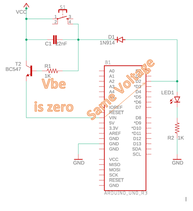
My circuit below is remarkably similar to the one Russel posted and it has been tested with an Arduino UNO. It switches the twelve volt supply pre-regulator.

The push button injects current into the NPN transistor which in turn injects current into the PNP transistor that powers up the Arduino. With the UNO the capacitor is required because it takes a long time for the UNO to start up and to set the ON_PIN high. The capacitor discharging through the 5k6 resistor keeps the base of the NPN supplied with current until the ON_PIN takes over.

The circuit on the left with the diodes allows further push button presses to be sensed so that you could signal other functions to the code or, as I do, use it as an abort.

I have used variants of this circuit with batteries to power IR and WiFi remotes using other MCUs, e.g. Adafruit ItsyBitsy. When the circuit is off the leakage current is under 1 micro amp making batteries last months between charges. Circuit values have to be adjusted for other supply voltages.
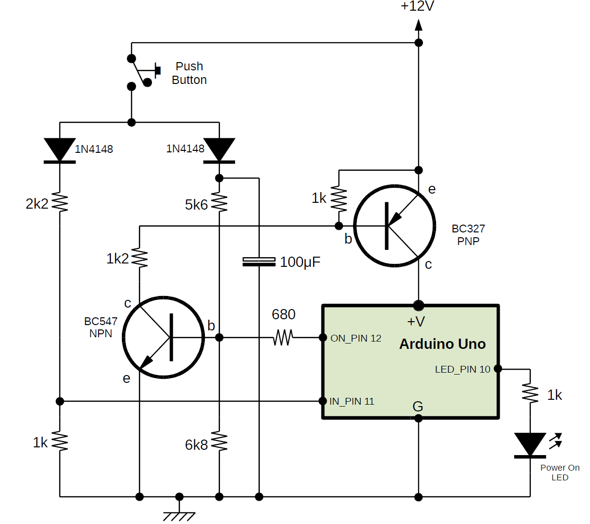
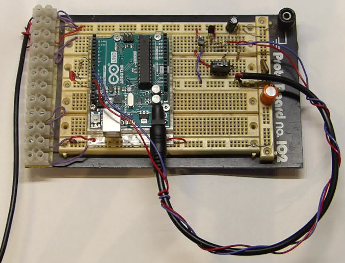
Arduino AutoPower circuit

enter image description here

The above is a solution to your initial problem but, to answer some of your questions:

For the BJT circuit, it turns on when the button is pressed because current can flow into the base of the transistor from the supply which is at a higher voltage than the emitter of the transistor. However, it doesn't work when the CPU output D2 should take over because, to turn the transistor on the base has to be around 0.6 volts higher than the emitter. The output pin can never supply more than the Vin of the CPU but Vin is provided by the emitter of the transistor. This is a vicious circle and current can never flow into the base of the transistor because the base voltage never gets high enough. Add in the 0.6 volts drop in the diode forward voltage and the situation is made worse. That is why I use a PNP for the switching. If the emitter is connected to the supply then you just have to connect the base towards ground through a resistor to turn it on.

For the FET the answer is similar but, as others have said, the current needed by the gate of the FET is tiny, and the charge on the gate of the FET will hold it on until it leaks away. There is no mechanism in the circuit to actively discharge the gate when the D2 output is pulled low and that is why it doesn't switch off under D2 control.

You say, "Presumably this is due to the 100uF capacitor", exactly. The capacitor charges almost instantly from the push button and discharges at a rate controlled by the 5k6 resistor. With other boards (ItsyBitsy and Feather) I didn't need the capacitor but, with the UNO I did. The start up time that I saw was around 1.5 seconds.

Another feature of my circuit that I like is that, although it is started by a button here, it can cactually be triggered by any sensor that can provide enough current to turn on the base of the BC547, e.g. a door switch, a temperature or light sensor going above a threshold, etc.

\$\endgroup\$
3
  • \$\begingroup\$ Thanks for this, I've tested it and it works great. I like the idea of the button input. Although you didn't answer my specific question, I've selected your answer as the correct one due to the extra feature, it works and so that it will pop up to the top so that others may benefit from it. Thanks again. \$\endgroup\$
    – GMc
    Commented Mar 24, 2020 at 1:35
  • \$\begingroup\$ Oh, and one more great feature is that this circuit works best with a push button. The Arduino seems to need around 3/4 of a second to "boot up". That is, there is roughly a 3/4 second delay between when the button is pressed and the Arduino can bring the power control line (pin 12 above and pin 2 in my project) HIGH to keep the power on. The above circuit allows for a momentary touch of the button (well under 3/4 seconds) and keeps the power alive long enough for the Arduino to boot and turn on D12 (or D2 in my case). Presumably this is due to the 100uF capacitor. \$\endgroup\$
    – GMc
    Commented Mar 24, 2020 at 2:04
  • \$\begingroup\$ Hi, thanks for your kind comments. You are correct, I didn't exactly answer the questions, I just provided a canned solution to your original problem. So, to put the record straight please see my edits above. \$\endgroup\$
    – user241457
    Commented Mar 25, 2020 at 8:37
13
\$\begingroup\$

I'm not convinced that this is the most elegant circuit / method to achieve what you want (switching on/off your Arduino). More on that below.

But anyway, my guess is that the main difference between the circuits is that the NPN transistor needs a (small) base current in order to conduct. That base current can only flow when C1 (22 nF) is being charged. As C1 has a very small value, charging it takes only an instant, then there's no more base current, Q1 switches off, the Arduino stops as it has no supply voltage.

The MOSFET doesn't need a current, it just needs a voltage. The gate of a MOSFET is isolated so no current can flow. The only way that C1 can charge is through the leakage current of D1. Wow, that's scary, relying on a diode's leakage current! No experienced circuit designer would do that willingly.

All-in-all your circuit creeps me out, I would never do this like that. What would I do then? First of all, letting some circuit switch on/off its own power supply is always a bit scary and actually not needed. I have made a project where an Arduino runs on 2 AA batteries in series and is continuously connected to the battery. Those AA batteries last for more than a year.

For this I removed the voltage-regulator chip on the Arduino board (leaving it in place and using the 3.3 V supply pin might also work) then I programmed the Arduino such that it goes into sleep mode most of the time. In sleep mode it consumes very little power.

I suggest that you find similar battery powered Arduino projects and see how they do that, then just do the same.

\$\endgroup\$
8
  • \$\begingroup\$ See my comment on OP's answer. His original cct works only by a fluke with MOSFET and cannot work with bipolar. The MOSFET turnoff is probably driven by reverse leakage of the diode !!! \$\endgroup\$
    – Russell McMahon
    Commented Mar 11, 2020 at 11:22
  • 2
    \$\begingroup\$ @RussellMcMahon The MOSFET turnoff is probably driven by reverse leakage of the diode !!! Ahem, see my answer: The only way that C1 can charge is through the leakage current of D1 \$\endgroup\$ Commented Mar 11, 2020 at 11:57
  • 1
    \$\begingroup\$ We agree :-). I can't see how the FET ever turns ON. It has a Vgsth of 4+ volts but no obvious way to EVER be forward biased. I suspect that what he is doing and the cct differ. || I have no problem with self-disabling ccts & have used them at various times. If an ATMega was your sole target then sleep mode is effective enough. Other circuitry may be less flexile. I know you know that. A two transistor circuit is usually most convenient so the switch is in the high side and responds to a high on and high hold signal. The 2nd transistor is high triggered and pulls the switch gate/base low. \$\endgroup\$
    – Russell McMahon
    Commented Mar 11, 2020 at 12:18
  • \$\begingroup\$ @RussellMcMahon The NMOS never fully turns on, when the switch is closed then gate-drain are shorted so the NMOS becomes an "NMOS diode" meaning it will drop somewhat more than its \$V_{threshold}\$. You can also consider it a source follower where the gate is at supply voltage. After the switch opens the 22 nF holds this situation (Vgd = 0) but is immediately being charged by D1. I could be happy with a self-disabling circuit using a PMOS. With an NMOS you'd have to switch the ground which is asking for trouble. \$\endgroup\$ Commented Mar 11, 2020 at 12:38
  • \$\begingroup\$ I agree with you that it is not the most elegant solution (it doesn't work how I want it to) but there is a bit of a learning curve for me - hence my question. Thanks for your, @russellmcmahon and the other replies. I will experiment further and hopefully not kill or maim any innocent Arduinos along the way! \$\endgroup\$
    – GMc
    Commented Mar 11, 2020 at 21:36
13
\$\begingroup\$

The transistor requires that the base have a higher voltage than the emitter to turn on. However, when the power from the button goes away, you can see that the only voltage that is applied to the base .. comes from the emitter! (through the Arduino and its diode, but still: that just guarantees that the base voltage is lower than the emitter voltage).

Bipolar transistors require a continous flow of current. As soon as they are deprived of current through the base, they turn off.

In the MOSFET case, the transistor is being held on by its own capacitance. There's actually no way it can be pulled low other than by leakage back through the diode. Current does not flow from the gate to either the drain or source.

The transistor approach could probably be made to work by changing it to a PMOS which requires being held low to turn on.

Edit: Falstad simulation with the Arduino replaced by a wire, which shows it initially turning on (pulse through C1) then very slowly turning off as leakage through the diode. Falstad doesn't simulate capacitor leakage, which may also be relevant.

\$\endgroup\$
1
  • \$\begingroup\$ See my comment on OP's answer. His original cct works only by a fluke with MOSFET and cannot work with bipolar. The MOSFET turnoff is probably driven by reverse leakage of the diode !!! \$\endgroup\$
    – Russell McMahon
    Commented Mar 11, 2020 at 11:22
7
\$\begingroup\$

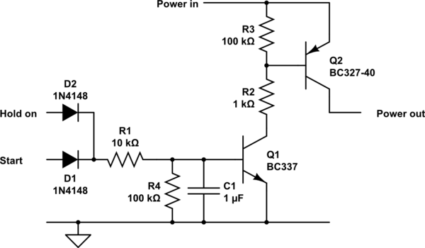
The circuit below will do what you want.
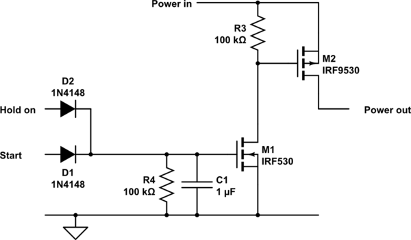
Direct replacement with suitable MOSFETs would also work.
Component values are correct as shown but could be altered to optimise results.

Many other small bipolar transistors will do what you want, but the ones I have shown (especially the BC327-40) are better suited to the task than many. The "-40" suffix means it has a high current gain and the BC327 / BC337 have a higher current handling capacity and lower Vsat (minimum turn on Vce) than most other small bipolar transistors. Despite the less usual BC suffix they are widely available internationally.

The BC327-40 will handle 100's of mA and has a voltage drop of perhaps 0.3V.
A suitably low Rdson MOSFET will produce minimal voltage drop in the same role.

Positive input at D2 or D1 will start or hold the circuit on.
Q1 turning on turns on Q2.

If required, turn off delay could be added by adding a capacitor from Q1 base to ground. A MOSFET in this location will allow a far higher value of R1, making turn off delay longer for a given C1.

schematic

simulate this circuit – Schematic created using CircuitLab

Here is a MOSFET version.
R1 & R2 in the bipolar circuit are not needed.
R4 and C1 set a turn off time constant - about 0.1 second as shown - so turn off times is 0.1 to a few tenthos of a second depending on the FET (lower Vgsth = longer turn off time).
MAny MOSFETs could be used - I've left the standard circuitlab defaults in place but they have much larger current and voltage capabilities than need, larger Rdson than necessary and Vgsth is OK for 5V and not low enough for 3V3 operation.

schematic

simulate this circuit

\$\endgroup\$
2
  • \$\begingroup\$ I've upvoted this answer so that it also hopefully stays at the top. This circuit also worked very well. However, I only tested the BiPolar transistor version so far. \$\endgroup\$
    – GMc
    Commented Mar 24, 2020 at 1:37
  • \$\begingroup\$ @GMc The "button" you refer to elsewhere is your S1 and my "Start" input. \$\endgroup\$
    – Russell McMahon
    Commented Mar 24, 2020 at 11:06
2
\$\begingroup\$

Your first schematic doesn't work because it's trying to pull itself out of a mire by his own hair.

An NPN requires its base voltage to be higher than the emitter voltage in order to conduct. Yet Arduino is powered via the same NPN's emitter, so it obviously cannot produce a pin voltage higher than VCC, so the NPN closes and the Arduino shuts down.

\$\endgroup\$
1
\$\begingroup\$

I don't understand the purpose of C1. IMO that's what could cause the fade-away. MOSFETS can stay on with very minimal current. Connect the gate to GND with a resistor between 22 to 100khoms. Also theorically, C1 should turn on the arduino when Vcc is powered up.

\$\endgroup\$
2
  • \$\begingroup\$ The idea for the capacitor was to provide a little bit of debouncing of the switch. Also as I think you are suggesting to provide a small window to allow the Arduino to start and raise D2. I will try the resistor tomorrow. \$\endgroup\$
    – GMc
    Commented Mar 11, 2020 at 21:27
  • \$\begingroup\$ GMc To debounce, you need to connect C1 to GND, not to Vcc. \$\endgroup\$
    – Fredled
    Commented Mar 14, 2020 at 21:47
1
\$\begingroup\$

In both the mosfet and bipolar circuits, the output (source in the mosfet and emitter in the bipolar) will always be less than the control voltage. Since the arduino output pin never can reach the supply voltage, as soon as you let go of the switch, the switched supply voltage drops and continues to drop. Using a PNP avoids that problem.

\$\endgroup\$
1
\$\begingroup\$

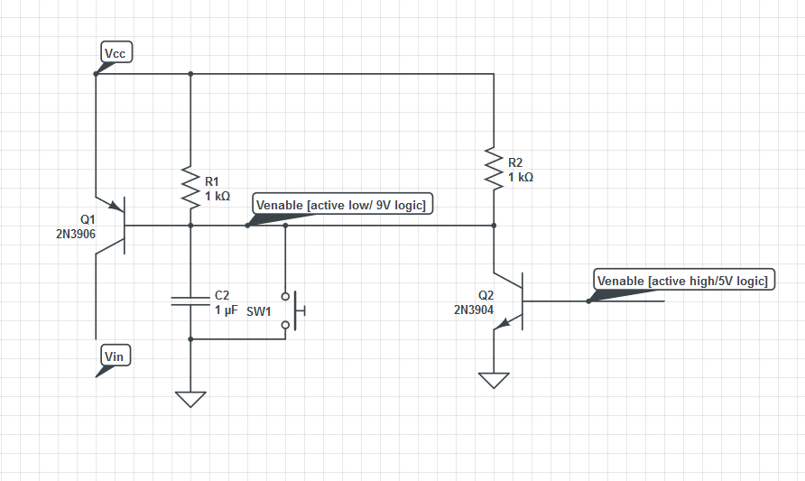
Use a PNP transistor and invert your logic.

enter image description here

enter image description here

\$\endgroup\$
3
  • \$\begingroup\$ When I built this circuit (two times) I found that I was only getting about 1-2 Volts between Vin and Gnd when I closed SW1. Q1 got very hot very quickly and eventually started smoking (after about 3-4 seconds). I triple checked the circuits before applying power and I believe I've followed the diagram correctly. \$\endgroup\$
    – GMc
    Commented Mar 24, 2020 at 1:55
  • \$\begingroup\$ @GMc It's very similar to my and other circuits. Change R1 to say 10k, remove R2 and add a 1k in series with the switch. Magic smoke is produced in Q1 by applying full Vcc to ground voltage to its be junction when the switch is closed. \$\endgroup\$
    – Russell McMahon
    Commented Mar 24, 2020 at 11:06
  • \$\begingroup\$ @GMc. I just noted that there is a direct path (with no resistor) between Q1 and Q2. Place a resistor between them that way Q2 will not drive Q1 extra hard. \$\endgroup\$ Commented Apr 20, 2020 at 23:37

Your Answer

By clicking “Post Your Answer”, you agree to our terms of service and acknowledge you have read our privacy policy.

Not the answer you're looking for? Browse other questions tagged or ask your own question.