0
\$\begingroup\$

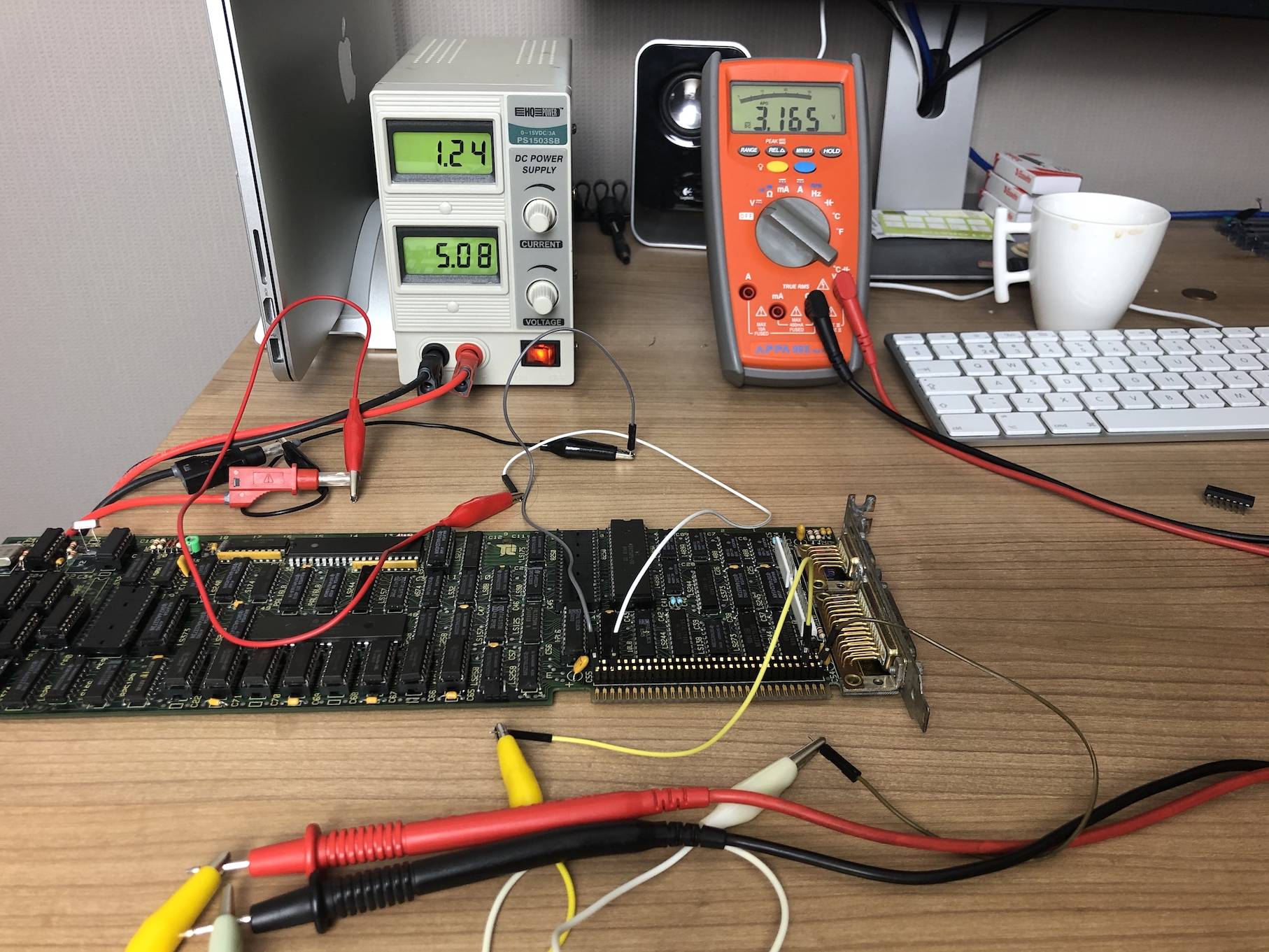
I am testing a video card and because I need to probe the logic chips on the 5V circuit I thought about hooking it up to my bench PSU. I am powering and measuring on the ISA pins where 5V and GND are exposed. The card has convenient headers for those

  • So bench supply is connected to B1 (GND) and B3 (+5v)
  • Multimeter is checking voltage on B31 (GND) and B29 (+5v)

What I noticed was that I am seeing a very low voltage on the power rail when it is powered like that. (I did the same with another videocard and I had the same readings).So that makes me think the issue is not related to the videocard itself. The PSU keeps saying 5.08V, so I don't see the voltage drop there. But I am seeing it with my multimeter.

When attached to a computer, that voltage drop on the power rail is not there, as it keeps outputting a clean 5V wen measuring with the same multimeter.

Why exactly is causing this on the bench setup ? I know that when something is shorting that I typically see it on the bench PSU (the voltage drops to almost zero). Here this is not the case as it remains on 5.08V and sees a steady current. Bot when measuring I only get 3.1v, meaning that all the logic chips also only get 3.1v so not really representative as a test.

enter image description here

\$\endgroup\$
1
  • \$\begingroup\$ If you are using cheap Chinese wires, they act more like resistors and less like wires. I had same problems, not knowing that these colored wires/cables were incredibly thin inside and of high resistance; you could literally use them as resistors, that's how bad they are. It's amazing to me how they even manage to make them of such a high resistance at such short lengths; I guess it's the incredible art of dirt-cheap crap-making. \$\endgroup\$ Commented Apr 1, 2020 at 10:03

1 Answer 1

2
\$\begingroup\$

Your problem: the series resistance of wires and contact resistances.

It looks to me that 1.24 A is flowing. You're using crock-clips, thin wires with "fragile" breadboard type connectors. That can easily cause a significant voltage drop at that current.

Confirm that by measuring at the supply output directly (you should get 5 V), then at the banana-crock clips (you will still get about 5 V), then at the crock-clip-thin wire (I guess you will get 4 V), then at the gold contacts on the card. Each measurement will give a lower voltage.

I suggest to solder some wire to the +5 V and ground rails, for example in parallel with one of the many decoupling capacitors on the card. Then make a solid connection from those wires to the supply. Maybe the supply has screw terminals, then use those. Prevent clips, connectors and contacts as much as possible.

\$\endgroup\$
1
  • 1
    \$\begingroup\$ 4.8v on start of crock-clip, 3.7v on the end of the crock-clip, 3.3v on the card .... wow ... did not know that would make such a huge difference. Never noticed that when playing around with Arduino's because current was a lot lower. Thanks a lot ! \$\endgroup\$
    – ddewaele
    Commented Apr 1, 2020 at 9:43

Your Answer

By clicking “Post Your Answer”, you agree to our terms of service and acknowledge you have read our privacy policy.

Not the answer you're looking for? Browse other questions tagged or ask your own question.