0
\$\begingroup\$

Power shield protection circuit specs

Hello! Iv'e been creating an ESP32 power shield and started designing the protection circuit for the power supply with the following features:

  1. Reverse polarity protection.
  2. Overvoltage protection.
  3. Overcurrent protection.

However, it is important to note that the design I'm using is based on this

Input

Supplied through either a 9V 2.5A power source to a screw terminal or a 9V 2.5A power charger to a barrel jack.

Output

The output of the protection circuit will be connected to 3 different regulators:

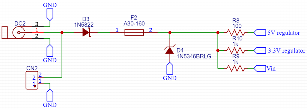
  1. Vin (Connected to internal ESP32 regulator that takes 3.3v 500ma at load).
  2. 3.3V 1A regulator.
  3. 5V 1A regulator.

Component links

I Chose the following components for the circuit:

  1. D3 (Schottky Barrier Diode)
  2. F2 (PTC Resettable Fuse)
  3. D4 (Zener Diode)

The PTC Resettable Fuse was chosen after reading this

Schematic

enter image description here

The Questions

  1. Do I need to put a series resistor with D4 or is the PTC Resettable Fuse sufficient ?
  2. Did i choose the correct PTC Resettable Fuse ?

P.S.

I'm new to electronics so please go easy on me if I miss obvious stuff.

\$\endgroup\$
1
  • 1
    \$\begingroup\$ You do not need D3 . In case of reverse polarity D4 will shorten circuit and fuse should trip. \$\endgroup\$
    – user263983
    Commented Dec 1, 2020 at 21:06

1 Answer 1

1
\$\begingroup\$

Your approach would work, at the expense of efficiency due to the diode drop on the input.

Here's a discussion on the topic: https://www.edn.com/protecting-against-reverse-polarity-methods-examined-part-1/

This device from Maxim provides overvoltage and reverse protection, with the addition of two FETs. It has no diode drop, so less power loss. More here: https://www.maximintegrated.com/en/products/power/protection-control/protection-ics/MAX4864L.html

Add a PTC of your choice in series and you would have a complete solution.

\$\endgroup\$
4
  • \$\begingroup\$ Hello! Thanks for the useful information source. I will definitely consider some of the designs there. However, regarding the protection ic - The efficiency is not the factor i'm looking to solve as to keep the circuit simple. In addition, you pointed out that I can add a ptc of my choice but my question is: did I choose the right ptc for the circuit above ? (I linked to the actual components i intend to use) \$\endgroup\$ Commented Apr 10, 2020 at 7:35
  • \$\begingroup\$ The difference in PTCs will be in how fast they activate. And with that, comes a tradeoff in voltage drop (efficiency again): the faster it acts, the more resistance it has to have. I think something rated in the 1.5 ~ 3A range can work. \$\endgroup\$ Commented Apr 10, 2020 at 20:00
  • \$\begingroup\$ The PTC I chose has an ih of 1.6A and It of 3.2A. however will the resistance it provides be sufficient from blowing the D4 diode which can tolerate only 5w ? I still cant figure out if the PTC I chose is correct and if I should add a series resistor to D4 or not. \$\endgroup\$ Commented Apr 10, 2020 at 20:15
  • 1
    \$\begingroup\$ Don't add the series resistance - you want as much of the IR drop to be in the PTC as possible so that it will trigger quickly. You can use 2 diodes in parallel to be safe. \$\endgroup\$ Commented Apr 10, 2020 at 20:24

Your Answer

By clicking “Post Your Answer”, you agree to our terms of service and acknowledge you have read our privacy policy.

Not the answer you're looking for? Browse other questions tagged or ask your own question.