0
\$\begingroup\$

I have the circuit below. Its a basic RC filter circuit with source impedance 50Ω from a signal generator, and load impedance 1MΩ||20pF from an oscilloscope at the output. The input voltage V2 is a 10kHz sine wave with 10V amplitude. enter image description here I need to derive a two port representation of this circuit, but I don't really know how.
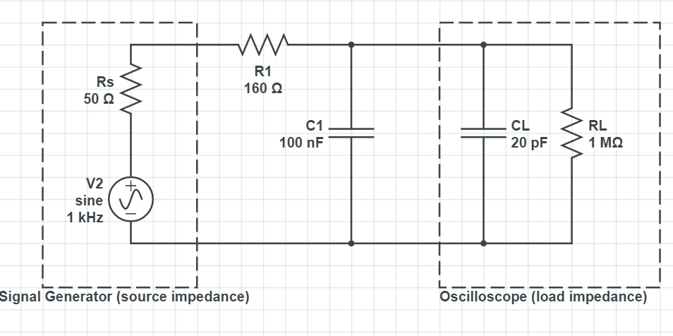
I am aware of the equations that relate V1, V2, I1 and I2 using Z or Y matrix parameters. I'm aware of how this circuit could be written as a voltage divider using impedances. What I don't understand is how to incorporate the source and load impedances, as well as both capacitors. I know that 1/(jωRC) gives the impedance of the capacitors but I don't understand how to make that into a real number.

I have input, output, gain and phase data at a range of frequencies. I believe I may need to use this somehow? I'm just not sure how.

Can anyone provide any insight, even if its just to point me in the right direction.

\$\endgroup\$

1 Answer 1

1
\$\begingroup\$

Can anyone provide any insight, even if its just to point me in the right direction

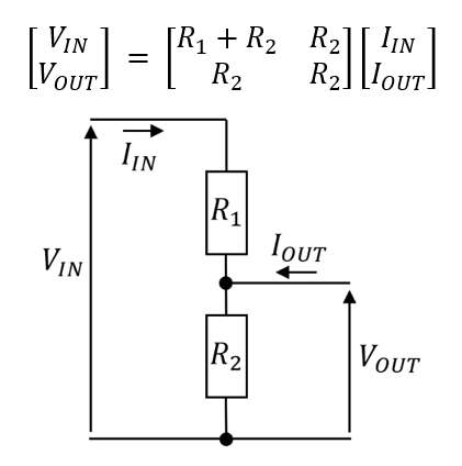
Here's a clue how to deal with a simple resistive potential divider: -

enter image description here

You will need to use C1 in place of R2 above but remember it's C1's impedance that replaces R2.

\$R_S\$ can be lumped in series with my R1 above.

CL can be lumped in parallel with your C1.

Can you take it from here?

I know that 1/(jωRC) gives the impedance of the capacitors but I don't understand how to make that into a real number.

You can't.

\$\endgroup\$
7
  • \$\begingroup\$ Thanks thats a good start, seems I was on the right track but I wasn't confident enough in my answers. Just a couple questions - you didn't mention RL, is that not needed or would it be lumped in parallel with R2. Also if you can't make the impedance of the capacitors real, does that mean I just leave jω in the answer? \$\endgroup\$
    – MendelumS
    Commented Apr 24, 2020 at 7:38
  • 1
    \$\begingroup\$ Yes, RL is in parallel with CL and C1 (replacing R2 in my math). Yes, jω is used. \$\endgroup\$
    – Andy aka
    Commented Apr 24, 2020 at 8:19
  • \$\begingroup\$ Perfect thankyou! Also is this using z or y parameters? \$\endgroup\$
    – MendelumS
    Commented Apr 24, 2020 at 8:36
  • 1
    \$\begingroup\$ The above is using z parameters. \$\endgroup\$
    – Andy aka
    Commented Apr 24, 2020 at 8:39
  • \$\begingroup\$ I've started going through it again but I'm still confused by the capacitors. Which value of R would I use for the impedance? I've added the capacitances since they're in parallel, but then when it comes to jωRC, do I use R = 1MΩ or 160Ω? \$\endgroup\$
    – MendelumS
    Commented Apr 24, 2020 at 10:03

Your Answer

By clicking “Post Your Answer”, you agree to our terms of service and acknowledge you have read our privacy policy.

Not the answer you're looking for? Browse other questions tagged or ask your own question.