2
\$\begingroup\$

I'm making a PCB for an audio amplifier + power supply (circuit here).

The power supply voltage rails with my transformer end up being about +/- 37V, and I want to generate a 5V rail from this for powering some cooling fans on the same PCB. This is pushing the limits of a typical voltage regulator (e.g. the max. input of a L7805 is 35V).

I tried a DC/DC converter (a R-78C5.0-1.0) but this produces audible noise on a speaker at the amplifier output (I put 10 uF decoupling caps at the input and output). One thing I didn't try yet is the EMC filter suggested in the datasheet here.

I found "high-voltage regulators" (e.g. an LR8), but the max. output current is 30 mA, and my fans need about 100 mA.

Is there a better way for generating 5V from 37V without producing EMC that I can hear as noise on the amplifier?

UPDATE: I'm an idiot. It turns out the noise was coming from having some signal wires too close to the transformer. I rearranged everything and now I can use the DC/DC converter without producing any audible noise at the speakers.

\$\endgroup\$
4
  • \$\begingroup\$ It would be worth trying the pi filter from the datasheet, maybe look for fans which suit your available voltages better too. \$\endgroup\$
    – Colin
    Commented May 7, 2020 at 12:42
  • 5
    \$\begingroup\$ You're using the wrong fans for the task \$\endgroup\$ Commented May 7, 2020 at 13:40
  • 1
    \$\begingroup\$ Agreed with Chris; I'm not sure why you want to use 5V fans here. IME, 12V fans are more common (nearly all PC fans are 12V), which significantly reduces the voltage you need to drop and the current you need to supply. And if your case can fit three of them, you could think about putting them in series directly off your +37V rail. 24V fans aren't too hard to find either, and you might even find an off-the-shelf 36V fan available somewhere. \$\endgroup\$
    – Nate S.
    Commented May 7, 2020 at 21:18
  • \$\begingroup\$ I am in fact using PC fans, but they run at the perfect speed if you power them with 5V (fast enough to cool the heat sink, not so fast they make noise), and I wanted to avoid the complication of powering them with 12V and slowing them down with PWM. \$\endgroup\$
    – Simon Coop
    Commented May 8, 2020 at 10:56

4 Answers 4

7
\$\begingroup\$

Custom regulator

Build your own linear regulator to get the flexibility you want, you won't need anything advanced here.

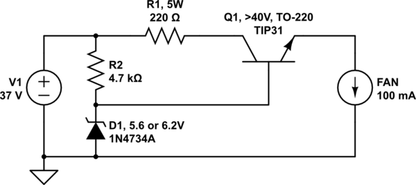
schematic

simulate this circuit – Schematic created using CircuitLab

Q1 is an emitter follower and R2+D1 sets the output voltage, which has to be about 0.6 to 1 V higher than what you want, because of the voltage drop through Q1's base.

R1 is optional and is just there to take some heat off of the main transistor. It may be easier to keep a power resistor cool or within limits, than it is to keep the transistor cooled. Without R1, Q1 will have to dissipate 3 watts, which requires a heat sink. If R1 is installed, Q1 should only dissipate 1 watt at most. R1 also acts as a crude current limiter, because the voltage will drop too much at high currents.

I just picked Q1 from something that seemed reasonable and existed in circuitlab. Which one you can get varies depending on where you live and where you order your components. It must be able to handle the voltage, current, and a couple of watts.

It's worth noting that no matter what you do, using a linear regulator such as this, a 7805, or an LM317, will necessarily create at least 3.2 watts of heat as losses, while delivering 0.5 watts to your fan. It does not scale well with multiple fans in parallel either, seeing how you would have to remove a lot of heat somehow.

Better solution

I noticed this:

[…] powering some cooling fans […]

If you have more than one fan, you should connect as many of them as you want in series, the optimal being 3 x 12 volt fans which you can connect directly to your unregulated supply.

\$\endgroup\$
3
  • 3
    \$\begingroup\$ +1, but generating >3 watts to run a fan to remove heat seems somewhat backwards. \$\endgroup\$
    – Colin
    Commented May 7, 2020 at 12:38
  • 3
    \$\begingroup\$ @Colin Especially since the fans themselves only need 0.5W. That's ~14% efficiency. Greta certainly won't be very happy about that. \$\endgroup\$
    – dim
    Commented May 7, 2020 at 12:46
  • \$\begingroup\$ Fans are a very nonlinear load, especially when starting up. So connecting the fans in series could burn them up. Putting a zener diode in parallel with each fan could avoid this. \$\endgroup\$
    – jpa
    Commented May 8, 2020 at 5:41
9
\$\begingroup\$

Look at it this way - you've found a weakness in your amplifier so, if you solve that you'll be in a much better position to cope with all sorts of EMI issues that can occur from time to time in pretty much all designs.

EMI is always produced by a switching regulator so your options are: -

  • Choose a linear regulator (and a big heat-sink with significant power loss) or,
  • Solve the basic problem with your amplifier or,
  • Pick fans that run on a higher voltage
\$\endgroup\$
2
  • \$\begingroup\$ Good point! Any suggestions on how to reduce the susceptibility of the amplifier to power supply noise? \$\endgroup\$
    – Simon Coop
    Commented May 7, 2020 at 10:53
  • \$\begingroup\$ There could be many, many reasons why it's susceptible. The devil's in the detail. \$\endgroup\$
    – Andy aka
    Commented May 7, 2020 at 10:59
2
\$\begingroup\$

As you already have a transformer as the main power supply and have AC voltage available in the circuit, you could use a transformer to generate the +5V supply also.

If the transformer is of a toroid type, it is often easy to add an extra winding on top of the existing ones. Just wrap wire around the core until output voltage is about 7 volts AC, then rectify it and use 7805 to regulate it to 5V.

If you cannot add an extra winding to the transformer, you could use a small secondary transformer. You can feed it either from the mains AC supply, or from the ~37 VAC supply from your primary transformer.

\$\endgroup\$
1
  • \$\begingroup\$ Yeah I thought about this but would prefer an on-PCB solution so there's not too many wires around. Maybe I'll go for the second smaller transformer to convert 37VAC to 5VAC. Thanks! \$\endgroup\$
    – Simon Coop
    Commented May 8, 2020 at 11:05
1
\$\begingroup\$

A note on that pi filter — if you just decouple the input of the switching regulator with a capacitor, that's fine for making the regulator happy, but on its own, it's not a filter.

The lower the inductance of the wires bringing that power supply to the regulator, the less work the capacitor has to do, and the more EMI you'll see on those wires. You can view the inductor in the pi filter as deliberately raising that inductance, which makes the capacitor at the regulator input work harder, and "traps" the high-frequency component from flowing back to the power supply. Then we provide an extra capacitor (the other leg of the pi) on the power-supply end for good measure.

\$\endgroup\$
1
  • \$\begingroup\$ Thanks! I was wondering how that worked \$\endgroup\$
    – Simon Coop
    Commented May 9, 2020 at 6:41

Your Answer

By clicking “Post Your Answer”, you agree to our terms of service and acknowledge you have read our privacy policy.

Not the answer you're looking for? Browse other questions tagged or ask your own question.