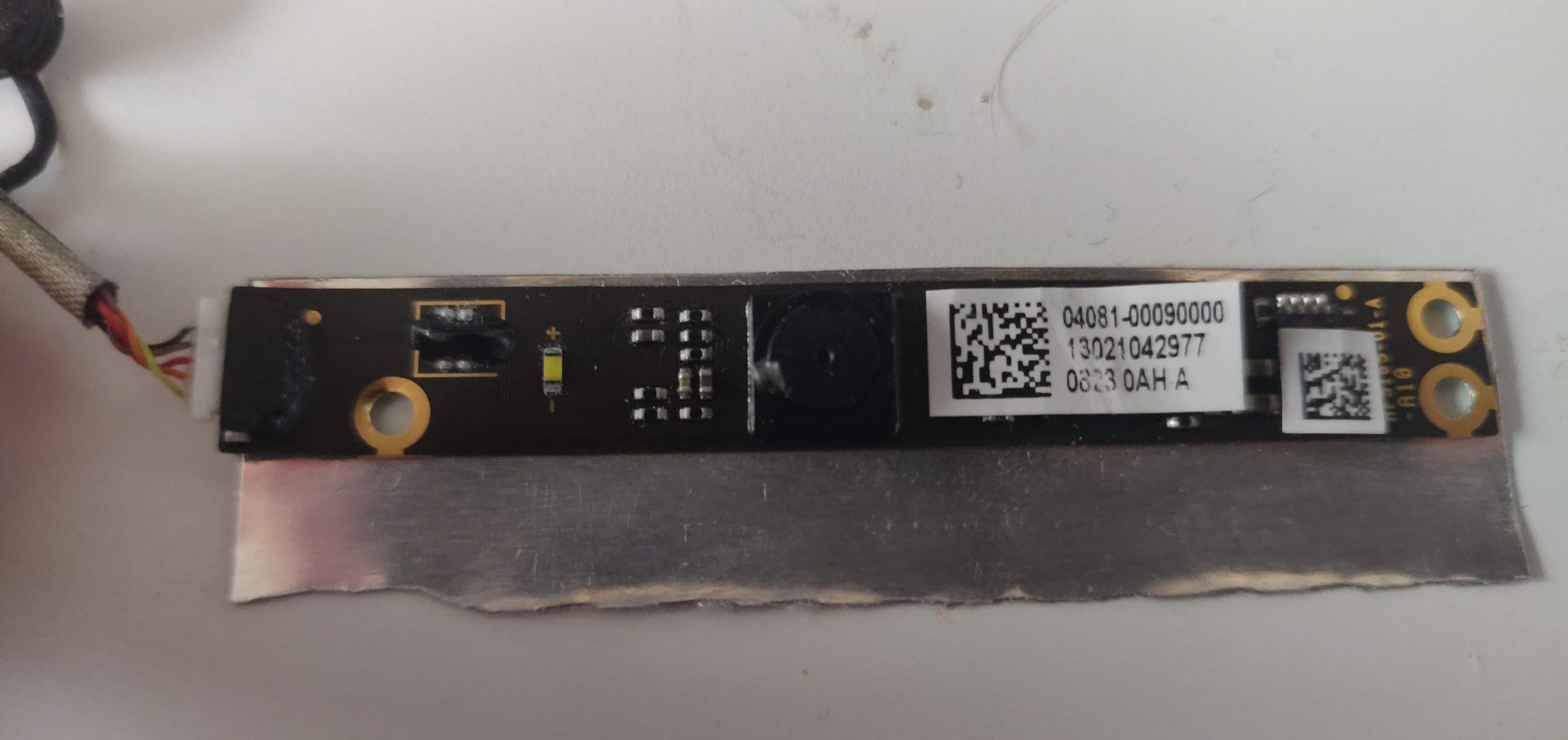
After seeing some youtube videos, I wanted to reuse an old laptop webcam and solder it to a USB cable.
This one comes from an ASUS X301A and looks like this:

AFAIK, The USB cable needs 4 wirings: VCC, ground, data+, and data-.
This webcam shows 5 wires, which I tried to identify. Red and brown wires were twisted together. I believe that I can guess data+ and data-, with no major risk for the camera, but VCC and ground should be strictly identified.
I will refer to 3 components:
- the ground ring
- the 4-pins component on top of it (A)
- the 2-pins component with plus and minus signs (B)
With a multimeter on beep mode, here are the wirings that I identified:
- Both orange and yellow wires are connected to ground
- A pins top-right and bottom-right, and of course B-, are connected to the ground
- The brown wire is connected to top-left A pin
- The red wire is connected to bottom-left A pin
My problem is that I could not identify any pin connected to the black wire or to B+. Moreover, the fact that 2 wires are connected to the ground looks a bit strange to me (why use 2 wires?).
Therefore, I am very confused about which wire to connect to the USB cable.
Based on this, is there a way I could identify which is which?
EDIT
As @Justme said in comments, beep mode is not sufficient, so here are the actual resistance values (2k ohms):
Multimeter's red on component, black on wire:
+--------+--------+------+------+------+------+------+
|        | ground |  A+  | Btl  | Btr  | Bbl  | Bbr  |
+--------+--------+------+------+------+------+------+
| black  |   0,42 | 0,89 | 0,47 | 0,47 | 0,47 | 0,47 |
| brown  |   0,42 | inf  | 0    | 0,64 | inf  | 0,64 |
| red    |    0,6 | inf  | inf  | 0,64 | 0    | 0,64 |
| orange |      0 | inf  | 0,85 |    0 | 1,5  |    0 |
| yellow |      0 | inf  | 0,85 |    0 | 1,5  |    0 |
+--------+--------+------+------+------+------+------+
Multimeter's black on component, red on wire:
+--------+--------+-------+------+------+------+------+
|        | ground |  A+   | Btl  | Btr  | Bbl  | Bbr  |
+--------+--------+-------+------+------+------+------+
| black  |    1,1 | inf   | inf  | 1,08 | inf  | 1,08 |
| brown  |   1,46 | inf   | 0    | 1,46 | 1,66 | 1,46 |
| red    |    1,5 | inf   | 1,67 | 1,46 | 0    | 1,46 |
| orange |      0 | 0,878 | 0,64 |    0 | 0,64 |    0 |
| yellow |      0 | 0,878 | 0,64 |    0 | 0,64 |    0 |
+--------+--------+-------+------+------+------+------+

Black=VCC,orange+yellow=GND, andbrown/red=data+/-. Does this seem right to you? \$\endgroup\$