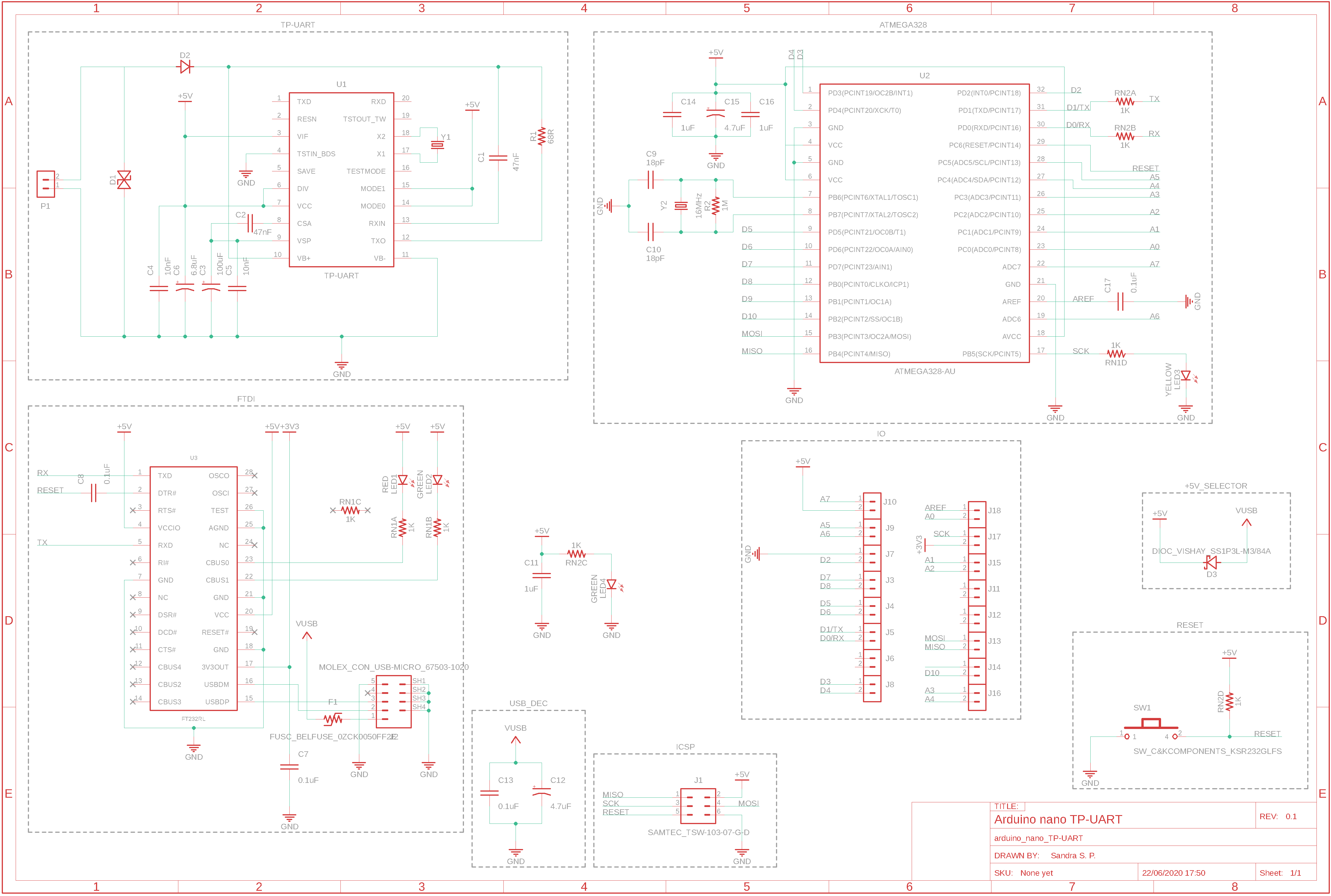
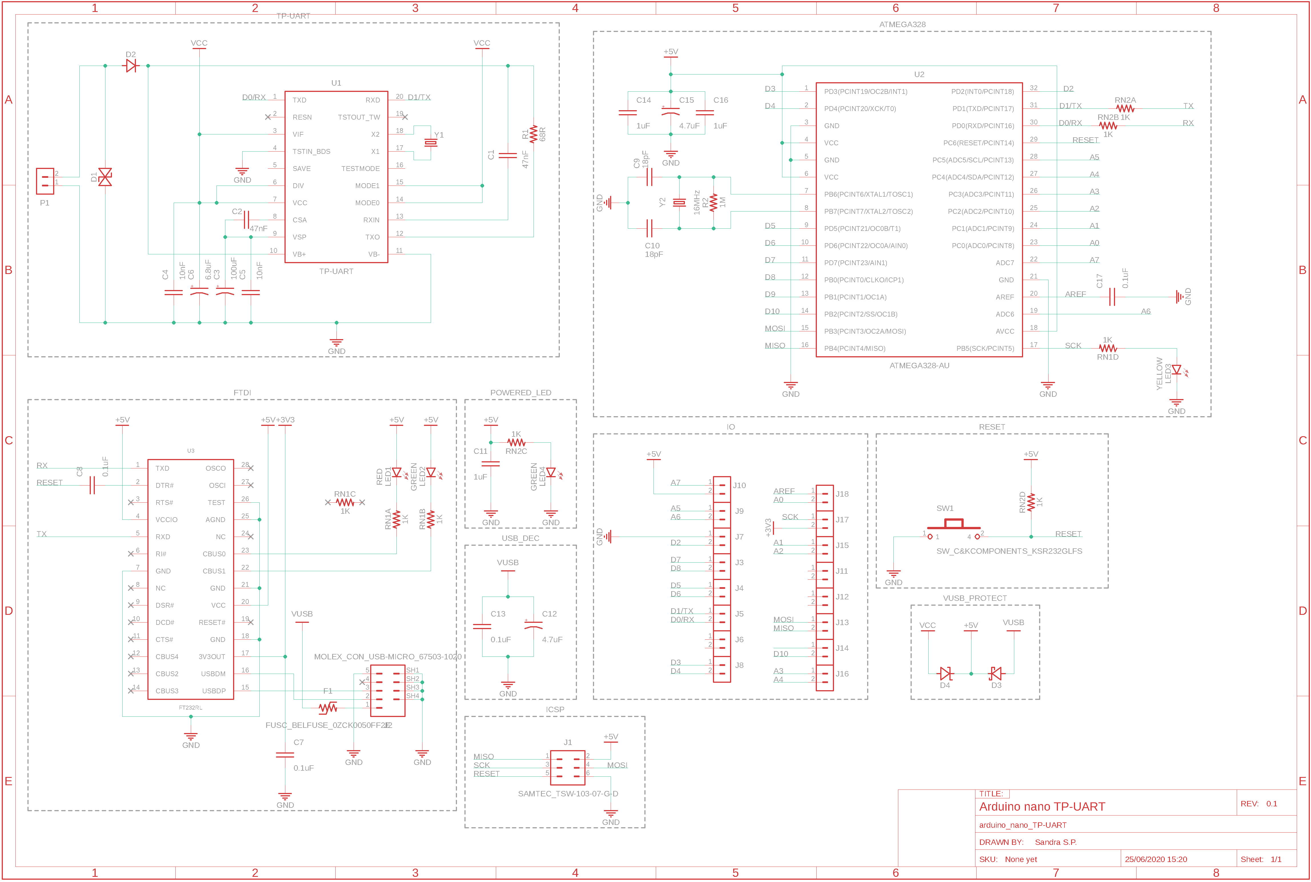
I'm working on a board that will include a TP-UART IC + an ATMEGA328-AU on the same device.
 I'm now facing the potential risk of damaging the host computer or the TP-UART IC if I'm mishandling the power source of the board.
The device can be powered through the KNX bus (typically 30V) and the TP-UART IC has its own built in regulator and will output 5V or 3.3V for an host MCU.
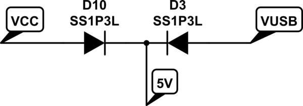
The thing is that I want to be able to power the device from VUSB (when I'm not connected to the bus) and I also want to be able to debug my firmware (so tied to the KNX bus AND the VUSB from the programer / computer)
I've seen some potential solution using P-channel mosfets / some autoswitchinp power mux (TPS2112) or even just opamp, but I really don't know what would be the safest and if there isn't any risks of back feeding 5V from VUSB to the VCC pin of the TP-UART IC
Edit: @akwky pointed out that if the board is powered by both P1 and VUSB, the internal on-chip regulator may have a slightly different voltage from VUSB. So I edited the schematic by adding a Zener diode Voltage Regulators (1SMA5918BT3G) to hopefully clamp the voltage to 5.1V going to VCC/VIF. Maybe I should have put this diode only on PIN 7 of the TP-UART. What do you think?


+5V_SELECTOR? \$\endgroup\$