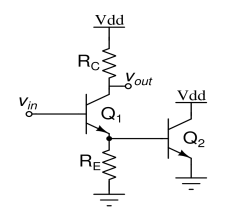
I have the circuit above for which I am supposed to find the voltage gain \$V_{out}\over V_{in}\$, but I don't understand what purpose the second transistor (right one, Q2) has here. If it wasn't present, I would have calculated \$dV_{out}\over dV_{in}\$ by differentiating \$V_{out}=V_{dd}-I_cR_c\$ where \$I_c=I_se^{V_{be}\over V_T}\$. Due to the presence of second transistor, a part of \$I_e\$ will flow in it, which will in turn reduce \$V_e\$ of the first transistor. Can I get some hints on how to approach this problem? Are such circuits of any practical use?
-
21\$\begingroup\$ The function of Q2 appears to be "go up in smoke." Any appreciable current through its base-emitter junction would cause it to become a short circuit between Vdd and ground. \$\endgroup\$– JRECommented Aug 11, 2020 at 12:19
-
\$\begingroup\$ It makes a good Active "dummy load" \$\endgroup\$– D.A.S.Commented Aug 11, 2020 at 12:27
-
\$\begingroup\$ Ignoring that this is a useless circuit: What does the presence of Q2 mean for the voltage across \$R_E\$? When V(\$R_E\$) = 0.5 V, what happens? When V(\$R_E\$) = 0.7 V, what happens? Whoever made this exercise should have connected the collector of Q2 to its base so that Q2 becomes a diode or (more advanced) ask why connecting the collector of Q2 like that isn't a good idea. \$\endgroup\$– BimpelrekkieCommented Aug 11, 2020 at 13:35
-
4\$\begingroup\$ "Crowbar protection" would be one legitimate use. At some value of Vin, the fuse in Vdd blows. I have heard of a similar circuit built into an audio mixing desk, with the express purpose of allowing recording engineers to terminate an out of control session (think "Spinal Tap") because of smoke coming out of the desk... \$\endgroup\$– user16324Commented Aug 11, 2020 at 14:46
-
1\$\begingroup\$ @BrianDrummond going up to 12 in this case \$\endgroup\$– user16222Commented Aug 11, 2020 at 15:00
2 Answers
Can I get some hints on how to approach this problem?
There are multiple ways to solve this circuit, one is putting it into a simulator. Considering that this is an assignment, I'd expect that you need to determine the base-emitter resistance of the second transistor which will be in parallel with \$R_E\$. The value of this depends on the operating point, so that might require whatever model you were taught in class.
After finding \$r_b\$ you can continue with your AC analysis.
Are such circuits of any practical use?
As you stated yourself, it is an assignment, I'd suggest not reading to much into it. The closest practical application I have encountered of this type of circuit is on-chip ESD protection (basically identical application to the crowbar protection user_1818839 mentioned) but it wouldn't be used as an amplifier of which you need to know the gain anyway.
The resistance of the base emitter junction of Q2 is in parallel with RE, otherwise I see no reason for Q2.If the resistance of RE is changed it will affect Vout. VDD will have to be quite low or Rcc quite high to prevent Q2 from burning up.

