1
\$\begingroup\$

How to make the output of a ring oscillator look more like a rectangular wave?

I have designed a differential ring oscillator whose output takes the following form:

enter image description here

The output of a ring oscillator should be in a rectangular shape. But the output of my ring oscillator resembles no rectangular shape. How can I correct this problem?

My design is a three-stage ring oscillator:

enter image description here

Each stage is a differential inverter:

enter image description here

I have tried the following tactics to make the output waveform looks more like a rectangular wave:

  1. Reducing the output capacitor
  2. increasing the source current in the differential inverters
  3. Increase the width of the transistors in the differential inverters

But all the above methods cannot yield the rectangular waveform. What other techniques I can use?

Thanks a lot.

\$\endgroup\$
18
  • 1
    \$\begingroup\$ The whole point of a ring oscillator is to run the inverters such that each one is contributing 60 degrees of additional phase shift beyond its natural 180 degrees from inversion. It is, inherently, going to be running flat out. There's just not going to be the high-frequency gain there to make the waveform square. The only way I can think to get a square wave out of one is to intentionally increase the capacitances, then follow it by a few stages of inversion to square things up. \$\endgroup\$
    – TimWescott
    Commented Sep 6, 2020 at 23:10
  • 2
    \$\begingroup\$ That's getting beyond my knowledge; when I design circuits, its at the board level, not in silicon. I wasn't suggesting putting more gates inside the oscillator -- I was suggesting following the oscillator with some gates to square things up, but only after putting in more capacitance to slow things down. \$\endgroup\$
    – TimWescott
    Commented Sep 6, 2020 at 23:52
  • 1
    \$\begingroup\$ @PhaeLeung Like Tim, this is outside my experience. But unlike Tim, he has a lot more experience than I do. That said, I do understand the circuit you provided. You will need to bring the signal out, somehow, and then apply gain and perhaps with positive feedback/hysteresis to square up the result. Since you have a current sink in each, would it be possible to increase the load seen by one stage (to pick off the signal) but also increase that particular stage's current sink to accommodate that requirement? (I don't like more stages as eventually this means harmonics are problematic, I think.) \$\endgroup\$
    – jonk
    Commented Sep 7, 2020 at 0:11
  • 2
    \$\begingroup\$ @RussellBorogove It's about \$2\frac13\$ cycles in \$1\:\text{ns}\$, from my reading. Somewhat higher than a few MHz. \$\endgroup\$
    – jonk
    Commented Sep 7, 2020 at 1:32
  • 1
    \$\begingroup\$ @PhaeLeung No, I meant after the "pick off" of the signal. Not within the ring, itself. I was just wondering if you could run one of the stages "a little hotter" than the others and use the extra drive current to support bringing a small signal outside the ring. (It seems like you'd need to do this anyway, as what's the point of having a ring if you don't use it? So I'm probably not seeing the whole picture of your question.) \$\endgroup\$
    – jonk
    Commented Sep 7, 2020 at 1:35

2 Answers 2

1
\$\begingroup\$

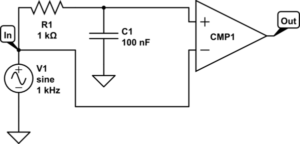
Easy peasy lemon squeezy. Just add a comparator that biases to the midpoint of the signal. They are basically op amps that run pole to pole. Here is the example circuit on the output.

schematic

simulate this circuit – Schematic created using CircuitLab

Note that R1 and C1 should adjust according to how often, if at all, the DC bias of your signal changes. If however your signal is AC coupled and has no DC bias of any kind then you can eliminate R1 and C1 and put ground directly to the positive of the comparator.

Also keep in mind the comparator will output its square wave rail to rail, so you either need to use positive and negative poles to get a ac-coupled output or you need to put an appropriate capacitor on the output to reject the DC bias if that is what you want.

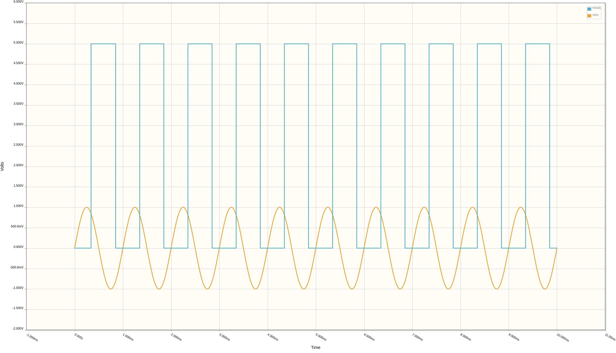
Here is the output from the simulation of the above circuit showing the conversion of the input sine wave into a square wave.

enter image description here

\$\endgroup\$
2
  • \$\begingroup\$ I see. Thanks for your ingenious solution. \$\endgroup\$
    – Underdog
    Commented Sep 7, 2020 at 4:15
  • \$\begingroup\$ @PhaeLeung Happy to help. Please dont forget to upvote and accept the answer if you feel it is appropriate. \$\endgroup\$ Commented Sep 7, 2020 at 4:21
1
\$\begingroup\$

If you want to preserve the phaseshifts of each stage, then load EACH stage with the identical and additional tap-off circuit.

Avoid positive feedback in the first stage of the tap-off circuit, because any snappy/abrupt edges will inject charges onto the RingOscillator capacitors.

Have that tap-off be an over-driven differential stage, with no feedback. Then the downstream circuit in each tap-off can be a positive-feedback circuit to provide the 50 picosecond edges you want.

=================================

regarding need for square edges: 10pF and 10picoSeconda at 3.3 volts will require

  • I = C * dV/dT = 10pF * 3.3v/10pS ==3.3 amps
\$\endgroup\$
1
  • \$\begingroup\$ Thanks all gain. Please excuse me for a follow up question. In a real application, is it necessary for a ring oscillator to have a nearly square waveform? For example, if the ring oscillator is used as a clock, I think it is necessary that the output waveform must be nearly a perfect square. This is why I insist to obtain a square waveform. Thanks a lot. \$\endgroup\$
    – Underdog
    Commented Sep 7, 2020 at 6:12

Your Answer

By clicking “Post Your Answer”, you agree to our terms of service and acknowledge you have read our privacy policy.

Not the answer you're looking for? Browse other questions tagged or ask your own question.