3
\$\begingroup\$

I have an audio sine signal -300mv to +300mv (600mv p-p), and I would like to read it using a microcontroller. I want to get rid of the negative half of the sine signal. How can I clip it?

I do not want to use a voltage divider to add DC bias to the signal because it may not be stable due to the power supply noise.

Also, the microcontroller accepts -0.5 to 6v on each pin. But is it OK to apply that signal for a reliable project forever.

\$\endgroup\$
2
  • \$\begingroup\$ Instead of clamping the signal you could you delta sigma ADC to read the signal. The readings would be much accurate. \$\endgroup\$ Commented Dec 24, 2012 at 21:08
  • \$\begingroup\$ If you're worried about power-supply noise getting into the DC bias from a voltage-divider, why not use a precision voltage reference? \$\endgroup\$ Commented Dec 26, 2012 at 22:24

3 Answers 3

3
\$\begingroup\$

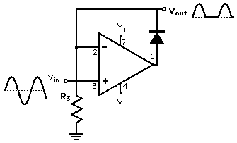
There are OpAmp circuits called precision clamp (or precision rectifier, or precision diode).

enter image description here (source)

Regarding the long term reliability. (The 2nd question in the O.P.)
If you current-limit the input to the microcontroller with a resistor, you could apply -0.3V to the pin for a prolonged time without permanent damage. Inportantly, the absolute maximum ratings are only about permanent damage, and not about performance. You may or may not get good A/D performance. Test it.

\$\endgroup\$
1
  • \$\begingroup\$ This circuit requires positive and negative supply voltages. I have only +5 voltage. I know I can use LM258 single-voltage but would the signal be distorted? \$\endgroup\$
    – yasserbn
    Commented Dec 24, 2012 at 21:36
2
\$\begingroup\$

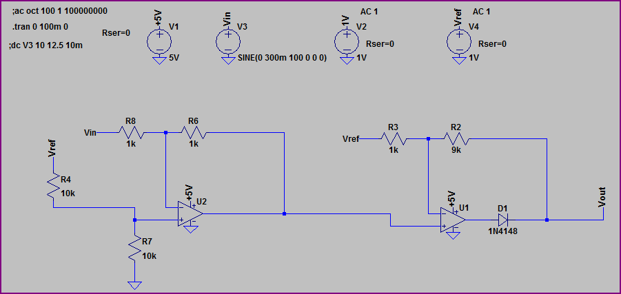
If you only have a single supply you can shift the signal before you rectify it, using something like the following circuit:

Rectify Shift

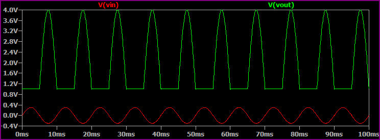
Simulation

Rectify Shift Simulation

You can change the Vref (a precision reference IC would be good here) and gain to suit your ADC input, and alter resistor values according to your source impedance, desired power draw, etc.

\$\endgroup\$
2
  • \$\begingroup\$ What software did you use to run the simulation? I don't recognize it. \$\endgroup\$ Commented Dec 26, 2012 at 22:24
  • \$\begingroup\$ It's LTSpice, an excellent free SPICE simulator from Linear Technology. \$\endgroup\$
    – Oli Glaser
    Commented Dec 26, 2012 at 22:51
1
\$\begingroup\$

You can AC couple the signal in and provide a working DC bias at mid-rail after the cap using resistors. the main problem with this approach will be that at the different frequencies your capacitor impedance will vary quite a lot. so this may not be the best solution.

\$\endgroup\$
9
  • \$\begingroup\$ I do not want to add DC bias using resistors. My power supply has a noise (100mv p-p) after filtering. I am looking for other approach. \$\endgroup\$
    – yasserbn
    Commented Dec 24, 2012 at 21:09
  • 1
    \$\begingroup\$ what makes you think that you're not seeing that noise on the ADC itself.? \$\endgroup\$ Commented Dec 24, 2012 at 21:11
  • \$\begingroup\$ Maybe the ADC has a band gap reference which reduces the problem? \$\endgroup\$
    – jippie
    Commented Dec 24, 2012 at 21:17
  • \$\begingroup\$ @rawbrawb: I am not using the ADC, I use the comparator to measure the frequency. \$\endgroup\$
    – yasserbn
    Commented Dec 24, 2012 at 21:22
  • 1
    \$\begingroup\$ bandgaps are REFERENCES not REGULATORS, there is a difference. THere are many different ways in which this may or may not help. I'm just saying there the OP is making assumptions that may not be valid unless he designed the chip itself. I'd say he should test it first. It may NOT work, but it may also improve his results. \$\endgroup\$ Commented Dec 24, 2012 at 21:22

Your Answer

By clicking “Post Your Answer”, you agree to our terms of service and acknowledge you have read our privacy policy.

Not the answer you're looking for? Browse other questions tagged or ask your own question.