1
\$\begingroup\$

I'm new around here :)

So, I am doing a university project regarding the effects of the output filter of a self-oscillating class D amplifier for low frequency audio signals, e.g. subwoofers. The project is mainly simulation based.

The overall idea is to use a powder core inductor driven into semi-saturation. The pros of this is that you can choose a smaller inductor and that the amplitude dependent change in inductance due to saturation will help stabilize the feedback loop, thus enabling higher gain in the loop and lower distortion. The main con is that the distortion is expected to increase as the core is saturated. So the goal is overall to maintain distortion performance with a smaller inductor.

My question is which effects (aside from hysteresis) will affect the distortion generated from the output inductor? I am thinking polarization and hysteresis, but frankly my knowledge in magnetics is fairly superficial.

Next question is which software can I use to simulate this? Effects such as the hysteresis loop is easy with a normal spice simulator, but I am unsure of other effects.

Any thoughts in general on the project?

\$\endgroup\$
1
  • \$\begingroup\$ Be careful of the core loss from driving a powder core in and out of semi-saturation. Some powder cores can heat up and go into thermal runaway. But if your project is "mainly simulation based" maybe you don't have to worry about it. \$\endgroup\$
    – John D
    Commented Sep 17, 2020 at 17:36

1 Answer 1

1
\$\begingroup\$

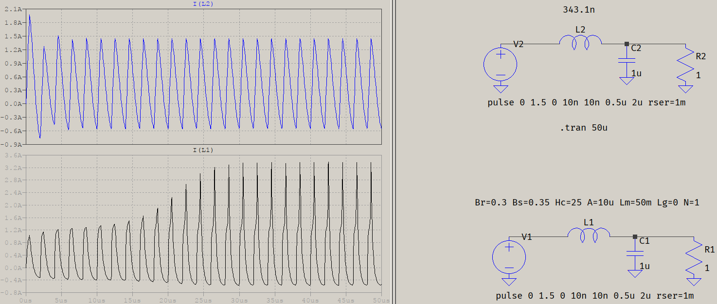
Polarization is just a matter of sign, while the hysteresis window is inherent to magnetic cores. What distorts the current is the B-H curve getting into the nonlinear region. Well, technically, it's not linear even in the "linear" region, but it has good linearity there. For ferrites (which you'll probably use), the B-H curves will be square-ish, so the linearity is even better. When you get into the saturation region, the core saturates, the permeability drops, so the inductance drops, causing the current to rise. The effect is a pointy current waveform, seen in L1 below (nonlinear core) vs L2 (equivalent linear inductance):

chan

If it's easier, think of the current mapped from a linear region to a tanh(), so the current will tend to be an atanh(). For small variations of B, H will rise exponentially.

The above is a Chan core, built-in in LTspice, but if you're looking for more accurate waveforms, you should look into the Jiles-Atherton model. If you integrate the voltage across the inductor and plot it agains the current through it, you'll see the B-H curve. For some differences between cores, see this.

\$\endgroup\$
1
  • \$\begingroup\$ Sorry about the late reply. Thank you for your insight, which has helped me in the project. \$\endgroup\$ Commented Dec 9, 2020 at 16:41

Your Answer

By clicking “Post Your Answer”, you agree to our terms of service and acknowledge you have read our privacy policy.

Not the answer you're looking for? Browse other questions tagged or ask your own question.