0
\$\begingroup\$

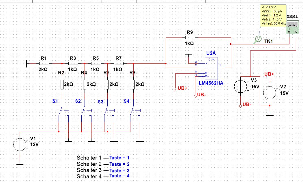
My school task was to simulate a 4BIT DAC converter in multisim. Im supposed to simulate the circuit when the switches are on/off and measure the output on the op amp.

I think the circuit works fine but I dont quite understand why the voltage is negative. I checked the poles and tried to invert reinvert it but nothing works. Is it standard for it to be negative? Or?

If my circuit is built wrongly please tell me how to fix it

Thank you very much

enter image description hereenter image description here

\$\endgroup\$
2
  • 1
    \$\begingroup\$ Since the opamp is in an inverting configuration (as it should be, to get a "virtual earth" at the DAC output) this is all as it should be. \$\endgroup\$
    – user16324
    Commented Oct 24, 2020 at 18:50
  • \$\begingroup\$ you want to know how to fix what? ... you have not said anything about any problems \$\endgroup\$
    – jsotola
    Commented Oct 24, 2020 at 19:08

2 Answers 2

4
\$\begingroup\$

As you're using an inverting amplifier, this is kind of expected – in fact, not only kind of. This is your design intent - inverting the voltage.

If you don't want inverted voltage, don't use an inverting amplifier configuration for your opamp, but a non-inverting one (there's gazillions of things on the internet about opamp configurations, do your own research. Even Wikipedia has a page on opamp applications).

\$\endgroup\$
1
  • \$\begingroup\$ Okay, I understand, thanks for your explanation \$\endgroup\$ Commented Oct 25, 2020 at 5:53
1
\$\begingroup\$

U2A is wired as an inverting amplifier so the positive current from the ADC network is converted to a negative voltage. To produce a positive output reverse the polarity of V1.

\$\endgroup\$
1
  • \$\begingroup\$ Yea I got it, thanks \$\endgroup\$ Commented Oct 25, 2020 at 5:53

Your Answer

By clicking “Post Your Answer”, you agree to our terms of service and acknowledge you have read our privacy policy.

Not the answer you're looking for? Browse other questions tagged or ask your own question.