0
\$\begingroup\$

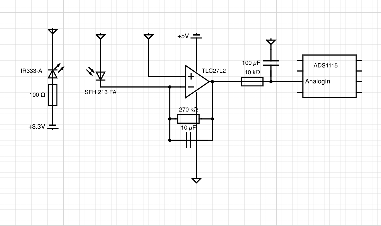
I'll start by saying I'm new to electronics, and have only minor working knowledge. I am designing a transimpedance amplifier to measure the opacity of a surface that is changing over time. The resulting voltage is sent into an ADC for me to record. My circuit is below:

enter image description here

I am seeing a lot of voltage variation due to the ambient temperature of the room (I've put a temperature sensor next to my TIA, and noted a strong correlation between a rise in temperature and a decrease in voltage). This variation is relatively large, and causes my measurements to have long cyclic behaviour (due to room heating turning on and off). FYI the ambient temperature changes by ~0.5std. Below is an example of the relationship I'm seeing (Blue is temperature, green is voltage):
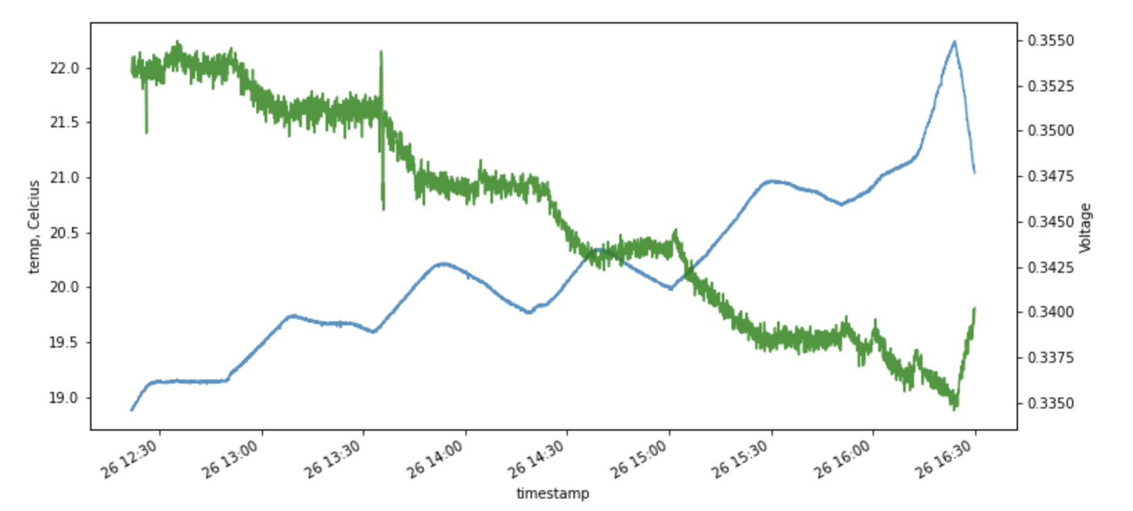
enter image description here (Blue is temperature, green is voltage)

My questions are:

  1. Is the variation in output caused by

    • the LED warming up, causing a decrease in light output?
    • the feedback resistor changing due to temperature changes?
    • both? maybe the photodiode?
  2. What are some possible solutions to correct for this, assuming I'll never have perfectly stable ambient temperature?

    1. I could add a thermsistor to the diagram, and use an input on the ADC to record the variation in temperature and use software to correct the op-amp output voltage. This makes sense to me, but I've can't seem to find ppl doing this after some searching.
    2. Measure temperature and use a calibration curve to "correct" the reading back to 20C - is this going to be robust though?
    3. Some electronic solution? Not sure what that looks like.
    4. A PID controller that tries to stabilize the LED output (assuming it's the LED that is causing the variation).

Thanks for any suggestions!

\$\endgroup\$
12
  • \$\begingroup\$ What's the actual range of the output voltages that you're reading? \$\endgroup\$
    – John D
    Commented Oct 30, 2020 at 21:28
  • \$\begingroup\$ about 0V to 2V, I would tune the feedback resistor if it gets above that (the ADC's analog inputs shouldn't near 3.3V) \$\endgroup\$ Commented Oct 30, 2020 at 21:33
  • \$\begingroup\$ Do you get the same temperature gradient when the output is near 2V as you do when it's near 0V? And what kind of capacitor is that 10uF feedback cap? \$\endgroup\$
    – John D
    Commented Oct 30, 2020 at 21:35
  • 1
    \$\begingroup\$ Resistors are pretty stable over temperature, and the dark current v. temp curves on the datasheet don't look like they should cause a significant error over a few 10s of degrees. The op-amp has lots of open-loop gain so should be pretty accurate. Now electrolytic caps are very leaky and have strong temperature dependance of leakage current, so it's something to check. \$\endgroup\$
    – John D
    Commented Oct 30, 2020 at 22:53
  • 1
    \$\begingroup\$ @KalleMP so like adding temp. sensor + transistor + heating resistors onto the PCB that will approx. maintain a stable temp? That's interesting - would this need to be calibrated? \$\endgroup\$ Commented Oct 31, 2020 at 20:53

3 Answers 3

3
\$\begingroup\$

The temperature coefficient of resistors tends to be pretty low, compared to what (I understand) you are seeing, typically tens or hundreds of PPM (parts per million), but check the datasheet for your resistors to be sure. Consider using a constant current source to drive your LED, rather than a voltage source through a resistor. With only 100 ohms I suspect you'll have a pretty strong dependence on supply voltage.

Also check the datasheet for your photodiode. Some have a much different temperature coefficient when operated in photovoltaic mode rather than by controlling a current (the photodiode will produce some voltage when it sees light).

Your ideas about feedback to control the LED current also has merit, but you might also consider instead making an identical copy of the circuit. On the copy, don't have the light pass through the translucent material, but just directly illuminate the photodiode. Connect this circuit to another ADC input and use it as a reference for comparison. If the components are matched reasonably well, this will cancel out a lot of the temperature and/or voltage dependence you typically see.

Also, the ADS1115 has an internal voltage reference, so the ADC should give very stable readings when presented with a constant voltage. However, if your supply voltage varies, then any signal derived from your supply voltage also varies. While this circuit may not benefit from it a great deal, many sensor circuits are ratiometric, providing a signal that is proportional to the power supply voltages. In that case you want your ADC to use the supply rail as a reference, rather than a fixed voltage.

\$\endgroup\$
1
  • \$\begingroup\$ Thanks for the ideas - lots to test out. My 3.3V supply voltage is from an RPi, that powers the ADC and LED, and from what I've read, it's pretty stable. I'll investigate the photodiode, too. The copy idea sounds near-ideal, but that would mean the LED is the culprit, right? \$\endgroup\$ Commented Oct 30, 2020 at 22:57
2
\$\begingroup\$

Suspect the diodes first. Suspect the photodiode first. I don't think it's the LED, because I would expect the voltage across the LED to go down with increasing temperature, causing the current to go up.

The leakage current in the photodiode is probably the culprit. Basically, as the temperature goes up, the photodiode will become more conductive. While this shouldn't make a difference (because the op-amp is holding the diode voltage to zero), I suspect that it's still allowing carriers to recombine in the diode, instead of getting out where they can affect the diode's terminal voltage.

So you really want to bias the photodiode into photoconductive mode. By doing this, you'll make sure that the carriers get swept out of the junction before they have a chance to recombine.

You probably want to do this by running the anode of the photodiode at some negative voltage -- I'd get a charge pump chip and run it at -5V or -10V. In the absence of a charge pump chip you can use a 555 and some diodes.

Actually -- if you have easy access, try it first with a 9V battery. If it works, then make your charge pump.

\$\endgroup\$
4
  • \$\begingroup\$ Thanks for the suggestion, Tim. Can you explain why I want to use the photoconductive mode for this problem? \$\endgroup\$ Commented Oct 30, 2020 at 23:47
  • \$\begingroup\$ Answer edited. But the truth is, it just feels right to me. So -- I could be all wet. But I still think I'm right! \$\endgroup\$
    – TimWescott
    Commented Oct 30, 2020 at 23:55
  • \$\begingroup\$ Photoconductive will be faster (which probably doesn't matter in this application) but noisier. In my experience if an optical setup has temperature dependence, the first place to look is for physical motion of the optics coupling light into the photodetector. \$\endgroup\$
    – The Photon
    Commented Oct 31, 2020 at 2:39
  • \$\begingroup\$ Changing between photo-conduction and photovoltaic modes changes the transfer function and sensitivity a lot and may not be a practical option in all cases. The noise characteristics also change and may recommend a change one way or the other sometimes. \$\endgroup\$
    – KalleMP
    Commented Oct 31, 2020 at 9:20
2
\$\begingroup\$

Two things I'd add to what's already been said in a couple of good answers:

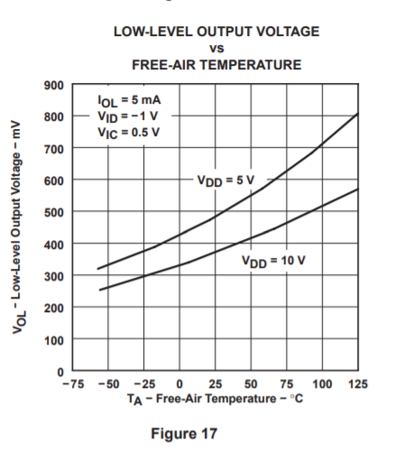
  • Even though the TLC27L2 says "rail-to-rail IO" on the front page of the datasheet, you should always look carefully at the specs to see what is meant by this claim. This chart from the datasheet shows that even though "rail-to-rail output" is claimed, you really can't count on output below about 500 mV.

    enter image description here

    (However the temperature dependence of this minimum voltage limit is opposite what you are seeing). You might also see something like the input offset voltage having much stronger temperature dependence when the inputs are near the voltage rails than at the mid-supply voltage where \$V_{OS}\$ is specified.

    Try adding a negative supply rail and see if it changes the behavior.

  • You haven't shared anything about your optical/mechanical setup, but often the optical coupling to a photodiode can be highly temperature sensitive, due to simple mechanical motion as components of the system expand or contract.

    If you can, try heating the optical system separately from the electrical circuit and vice versa to help narrow down where the problem is.

\$\endgroup\$
2
  • 1
    \$\begingroup\$ Great points, ty! I didn't consider the opamp having a temperature dependence, too. So the optical/mechanical setup suggestion is interesting (you can quickly get the gist of it here: controlledmold.com/building-a-bioreactor-vessel-and-structure). I'll try your suggestion of heating the two components separately as soon as I can. \$\endgroup\$ Commented Oct 31, 2020 at 4:11
  • 1
    \$\begingroup\$ @Cam.Davidson.Pilon to be honest that optical system should be pretty robust to small mechanical shifts. Possibly the LED wavelength is shifting with temperature, and that is changing the scattering coefficient (since scattering depends on the relationship between the wavelength and particle size). \$\endgroup\$
    – The Photon
    Commented Oct 31, 2020 at 4:57

Your Answer

By clicking “Post Your Answer”, you agree to our terms of service and acknowledge you have read our privacy policy.

Not the answer you're looking for? Browse other questions tagged or ask your own question.