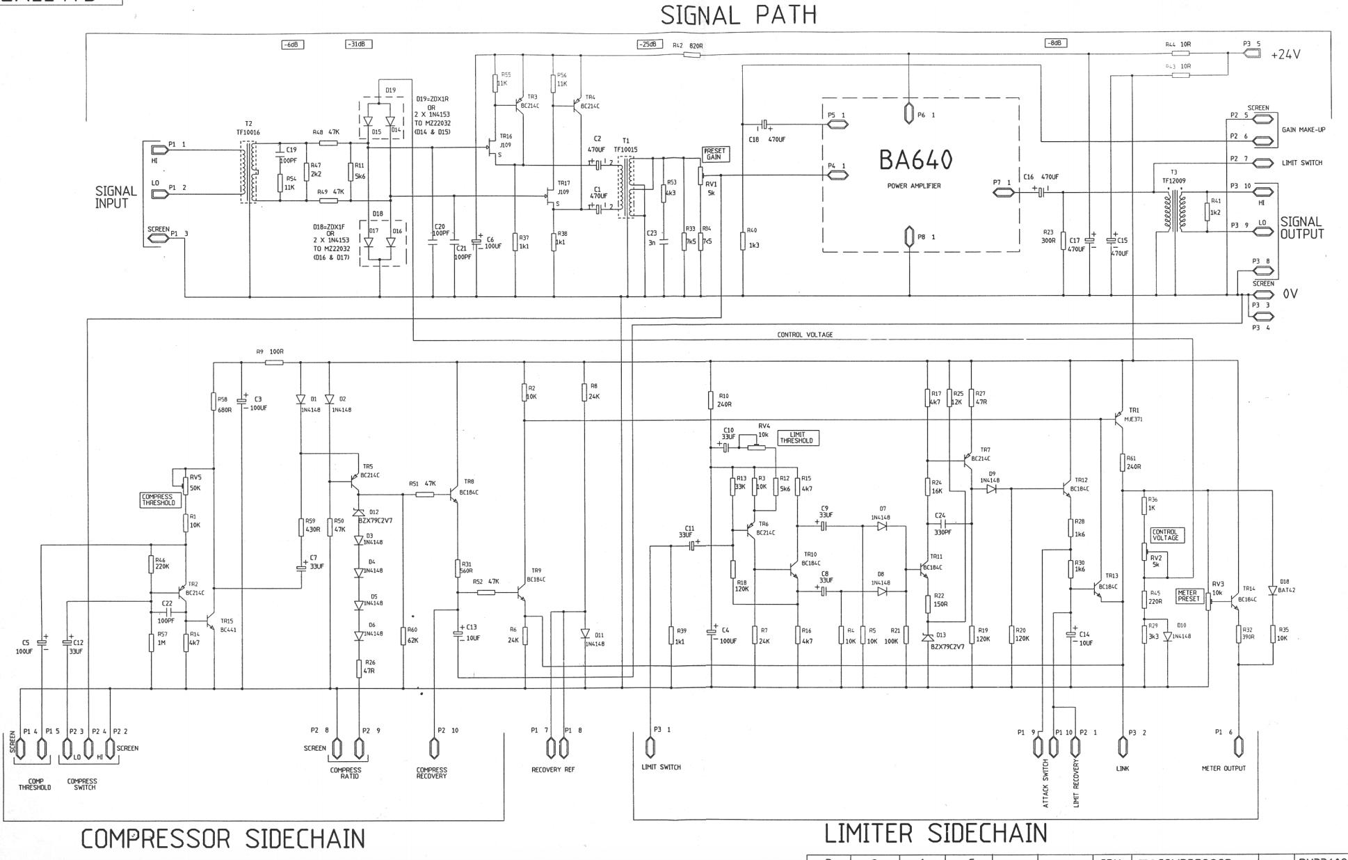
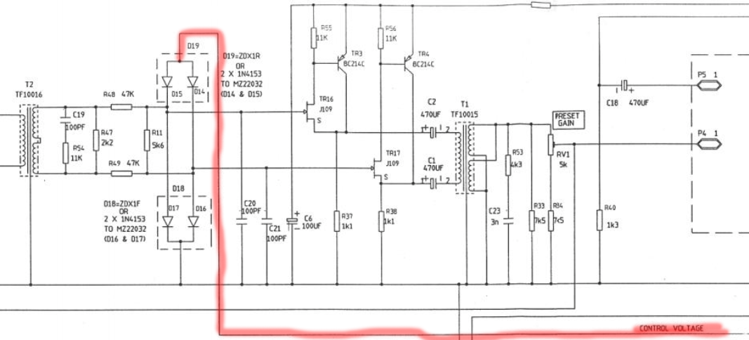
I'm analyzing the Neve 33609 schematic (as shown below), and I can't figure out what is responsible for rectifying the AC audio signal into a DC control voltage. If anyone has an idea what components are specifically responsible for rectifying, please let me know.
\$\begingroup\$
\$\endgroup\$
3
-
\$\begingroup\$ Why do you think that the signal has to be rectified? Diodes D18,D19 are limiter, they do limit the signal by cutting it. \$\endgroup\$– Marko BuršičCommented Dec 11, 2020 at 8:06
-
1\$\begingroup\$ Because the manual says that the sidechain turns the AC audio into a DC control voltage. And also because every diode bridge compressor uses a DC control voltage \$\endgroup\$– Gus the BusCommented Dec 11, 2020 at 8:09
-
\$\begingroup\$ The signal is only rectified on the limiter session, as per the techinical 33609 paper \$\endgroup\$– lucasCommented Jun 20, 2023 at 14:02
Add a comment
|
2 Answers
\$\begingroup\$
\$\endgroup\$
4
-
\$\begingroup\$ I saw the control voltage label, but the manual says very clearly that the sidechain turns the AC audio into a DC control voltage. My thought was that the rectifier would have to actually be in the sidechain rather than the signal path \$\endgroup\$ Commented Dec 11, 2020 at 9:31
-
\$\begingroup\$ The signal path carries on into amplifiers made of R55, TR3 & TR16, and R56, TR4 & TR17. \$\endgroup\$– ColinCommented Dec 11, 2020 at 9:41
-
\$\begingroup\$ nope, its taken off the signal path itself. You see, the audio signal is not referenced to the dc power supply. That is why it doesn't effect the signal. That is the advantage of balanced line stage, because the common mode noise has been nulled out from the DC supply. The only drawback is of course having to use signal transformers, that increase the cost of manufacturing. \$\endgroup\$ Commented Apr 12, 2021 at 18:45
-
\$\begingroup\$ No, the upper diodes are the attenuating element (the lower diodes are just for balancing impedance). That "CONTROL VOLTAGE" is actually a signal that matches the input so the diodes act like variable resistors. I'm not familiar with this particular schem so I can't say exactly where the DC offset is being generated but logic would suggest it's going to be around attack / release controls and I do see some diodes around there as well. Also, this schem is not complete. \$\endgroup\$ Commented May 16 at 20:49
\$\begingroup\$
\$\endgroup\$
How can it use a DC signal when a DC electronic signal is a constant voltage or current, meaning it does not vary over time. Its frequency is always going to be 0 Hz. It can also be represented as a flat line on a graph. An AC electronic signal, on the other hand, varies over time and therefore has a non-zero frequency, which is why the DC signal cannot be used and it must be D19.


