-1
\$\begingroup\$

I tried to design this without much success so any help would be appreciated.

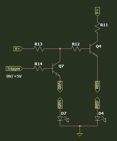
A circuit where initially in a 3-pin Bi-Color LED (Common Cathode), the red led illuminates. Then it switches off and the green led illuminates, when an external voltage is applied.

for example: initial state: external voltage 0V -> red led on, green led off

external voltage changes to 5V (or any) -> red led goes off, green led turns on

if the external voltage changes back to zero it resets the leds to the initial state.


--Just to clarify

This discrete (transistor) circuit is powered by a positive voltage supply between 15-45V. Being a transistor circuit the resistors can be adjusted for different voltages.

An external voltage that can be 0V or +5V will dictate which led lights up.

0V lights up the red led (initial state)

+5V turns off the red and lights up the green.

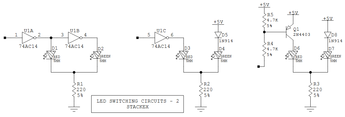
The transistor circuit that AnalogKid showed (third on the last image) fits the bill with the exception that it operates with Ground and +5V instead of the 0V and +5V required in this application.

This is what I had tried with V+ between 15-45V

enter image description here

I tried something along the these lines but could not get the same current on both leds. Also tried adding a trimmer to adjust the current (brightness) but that didn't work correctly, and that would be the preferred solution instead of replacing resistors to get the same brightness on both leds.

\$\endgroup\$
8
  • 1
    \$\begingroup\$ Welcome to the community!! This community expects you to show some efforts from your side. Try adding what your ideas are. \$\endgroup\$
    – G-aura-V
    Commented Dec 20, 2020 at 13:23
  • 1
    \$\begingroup\$ Does this answer your question? Device to power either a red LED or a green LED \$\endgroup\$
    – ocrdu
    Commented Dec 20, 2020 at 13:49
  • \$\begingroup\$ You will probably want some hysteresis in the circuit. What's powering the LEDs and circuit? What's the external voltage source you are observing with this circuit? You say 5 V (or any) but you really need to define what you really mean with better precision than that. Would 1 V change things? 0.5 V? Etc. Write a lot more. \$\endgroup\$
    – jonk
    Commented Dec 20, 2020 at 20:31
  • \$\begingroup\$ I just saw the clarification. If GND isn't 0 V, then what is it? AND, are the LEDs powered from the 45 V source? \$\endgroup\$
    – AnalogKid
    Commented Dec 20, 2020 at 21:44
  • \$\begingroup\$ Ground is just the label for what you decide is 0V. By definition, ground is 0V. It’s also arbitrary. You could take the 0V wire (black wire/ “-“ /ground) and 5V wire (red wire/ “+”) and instead declare the 5V wire as ground/0V. Now the wire that used to be ground (black wire) is -5V. Voltage is just a potential difference, analogous to potential energy from height. Ground is arbitrary and just means the reference you use as 0V and all voltages will be given in terms relative to their difference in volts from that point. \$\endgroup\$
    – metacollin
    Commented Dec 20, 2020 at 22:14

5 Answers 5

0
\$\begingroup\$

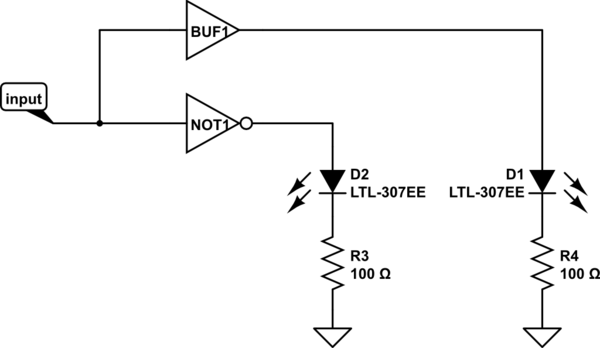
You could use digital logic elements and do something like this.

schematic

simulate this circuit – Schematic created using CircuitLab

If your input signal can directly drive the led then you can omit the buffer or if you want you can replace it with two sequential NOT to not have to use another component.

\$\endgroup\$
0
\$\begingroup\$

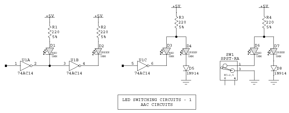
Here is something I've posted before with three methods. The middle schematic should work for you. You don't say if your LED is common-anode, common-cathode, or dual isolated LED chips. This schematic is based on a common anode part, but also will work with a dual-isolated part.

enter image description here

Because only one LED is on at a time, you can get away with only one current limiting resistor. Also, the gate can be replaced with one transistor. If you use a 2N7000, no additional parts are needed. With a bipolar thpe like a 2N4401, you need a base resistor.

The circuit works because the forward voltage of an LED plus a diode is less than that of an LED alone. When the input goes high and the gate output goes low, D3 effectively "shorts out" D4-D5.

Here is an updated version for common-cathode LEDs.

enter image description here

\$\endgroup\$
4
  • \$\begingroup\$ Sorry forgot to mention the dual led is Common Cathode. \$\endgroup\$
    – primare
    Commented Dec 20, 2020 at 15:19
  • \$\begingroup\$ Reverse the circuit, still works. \$\endgroup\$
    – AnalogKid
    Commented Dec 20, 2020 at 15:44
  • \$\begingroup\$ Thanks for your suggestion. Tried the one with transistor and it works, but requires -5V to turn on the green led and I only have a positive voltage available. \$\endgroup\$
    – primare
    Commented Dec 20, 2020 at 19:44
  • \$\begingroup\$ Which schematic are you using? In the -2 schematic, right side, 5 V or open circuit turns on the Green, and grounding R4 turns on the Red. \$\endgroup\$
    – AnalogKid
    Commented Dec 20, 2020 at 20:44
0
\$\begingroup\$

Here is a simple (one BJT) way of doing it.

schematic

simulate this circuit – Schematic created using CircuitLab

\$\endgroup\$
1
  • 1
    \$\begingroup\$ Yeah that does it. Thanks! I was trying a 2 transistor approach but this simpler. \$\endgroup\$
    – primare
    Commented Dec 20, 2020 at 22:43
0
\$\begingroup\$

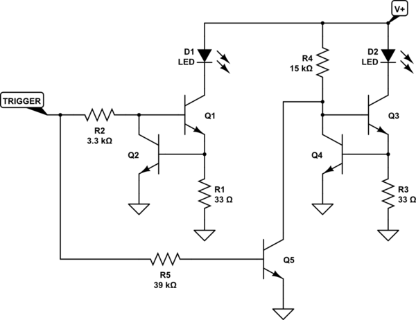
Now that you've actually posted a schematic you've tried, I have more information about what you are looking for. You could try something like this:

schematic

simulate this circuit – Schematic created using CircuitLab

It should work pretty well, without part changes, over the entire range you specify for \$V_{+}\$.

It's just two different current sink sections coupled by an input signal inverter (\$Q_5\$.)

\$\endgroup\$
4
  • \$\begingroup\$ I'll give it a try. Thanks for that. If you were to add a trimmer to one of the leds to adjust the brightness, how would you go about it? \$\endgroup\$
    – primare
    Commented Dec 20, 2020 at 23:45
  • \$\begingroup\$ @primare \$R_1\$ and \$R_3\$ set the currents. You could just change them until things "look right" to you. \$\endgroup\$
    – jonk
    Commented Dec 20, 2020 at 23:52
  • \$\begingroup\$ I did simulate this but it didn't work as expected. \$\endgroup\$
    – primare
    Commented Dec 21, 2020 at 12:29
  • \$\begingroup\$ @primare I also did simulate it and it works as I expected it to do. So it must be a difference of expectations. I'd be happy to show you my simulation results in the answer. \$\endgroup\$
    – jonk
    Commented Dec 21, 2020 at 17:50
0
\$\begingroup\$

Ok, so none of the other schematics actually meet your requirements.

To reiterate:

  1. The LEDs are common cathode.
  2. You want to drive them from a wide voltage range of 15-45V
  3. You want to control them via a logic level (5V) input and alternate red or green depending on if it is high or low.

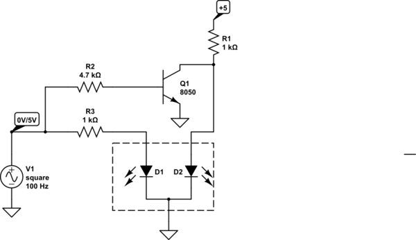
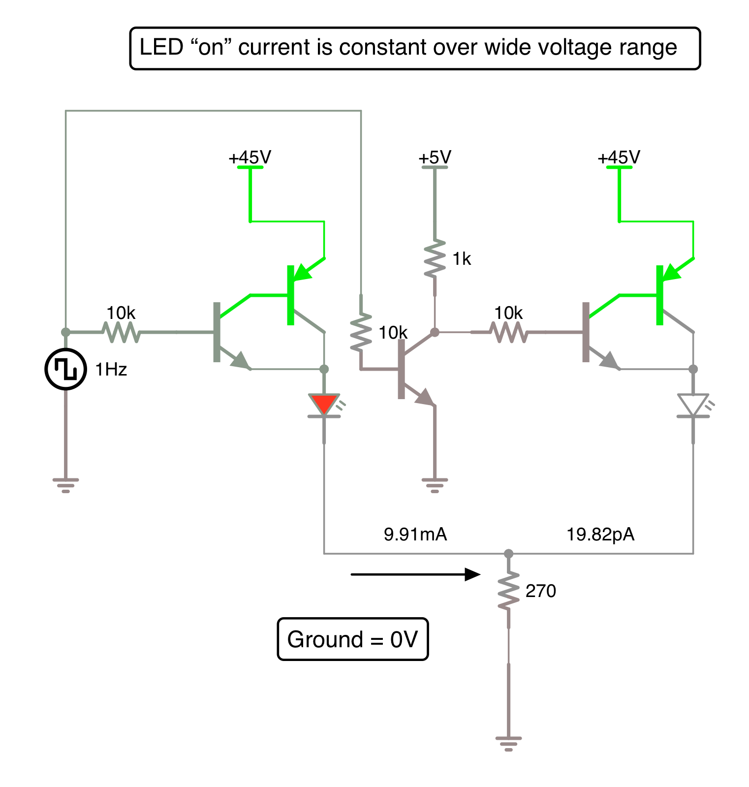
Here is a circuit that will actually do all those things. Additionally, the LED current is constant with changing drive voltage and set by the cathode resistor. The current will be (5V - LED voltage drop) divided by that resistance.

And yes, you only need three resistors. This circuit makes use of complementary feedback transistor pairs.

Your control input is where I have substituted a square wave input on the far left (it swings from 5V to 0V). Connect your control signal to the transistor bases. Ignore the ground that is also connected to the square wave - that was for simulation purposes.

enter image description here

\$\endgroup\$
1
  • \$\begingroup\$ Thanks for that. The main drawback I see with this is the need of two supply voltages, 45V and 5V. \$\endgroup\$
    – primare
    Commented Dec 21, 2020 at 9:11

Your Answer

By clicking “Post Your Answer”, you agree to our terms of service and acknowledge you have read our privacy policy.

Not the answer you're looking for? Browse other questions tagged or ask your own question.