1
\$\begingroup\$

Can I just use my oscilloscope to measure the voltage across a capacitor or will I need a function generator for that?

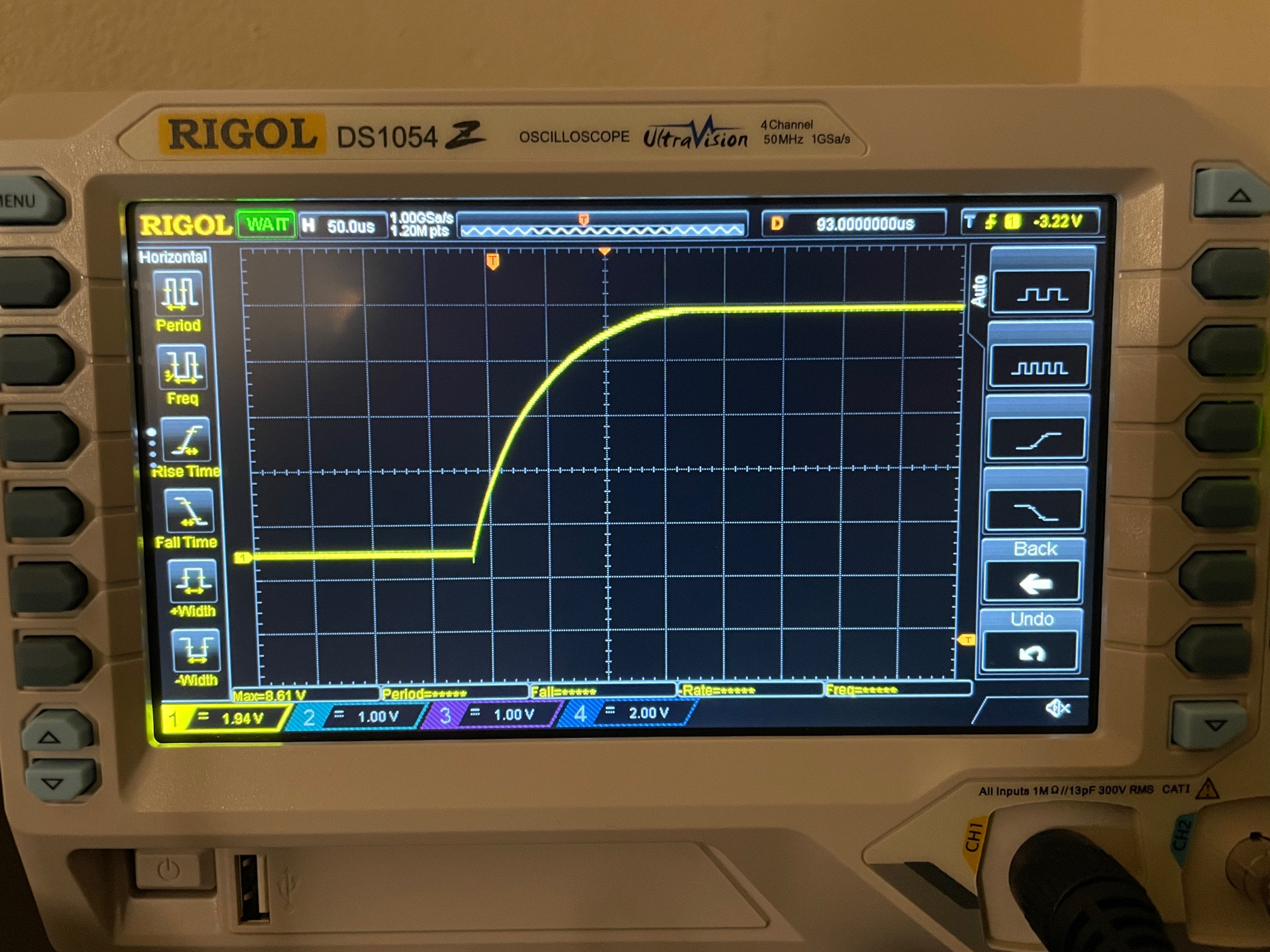
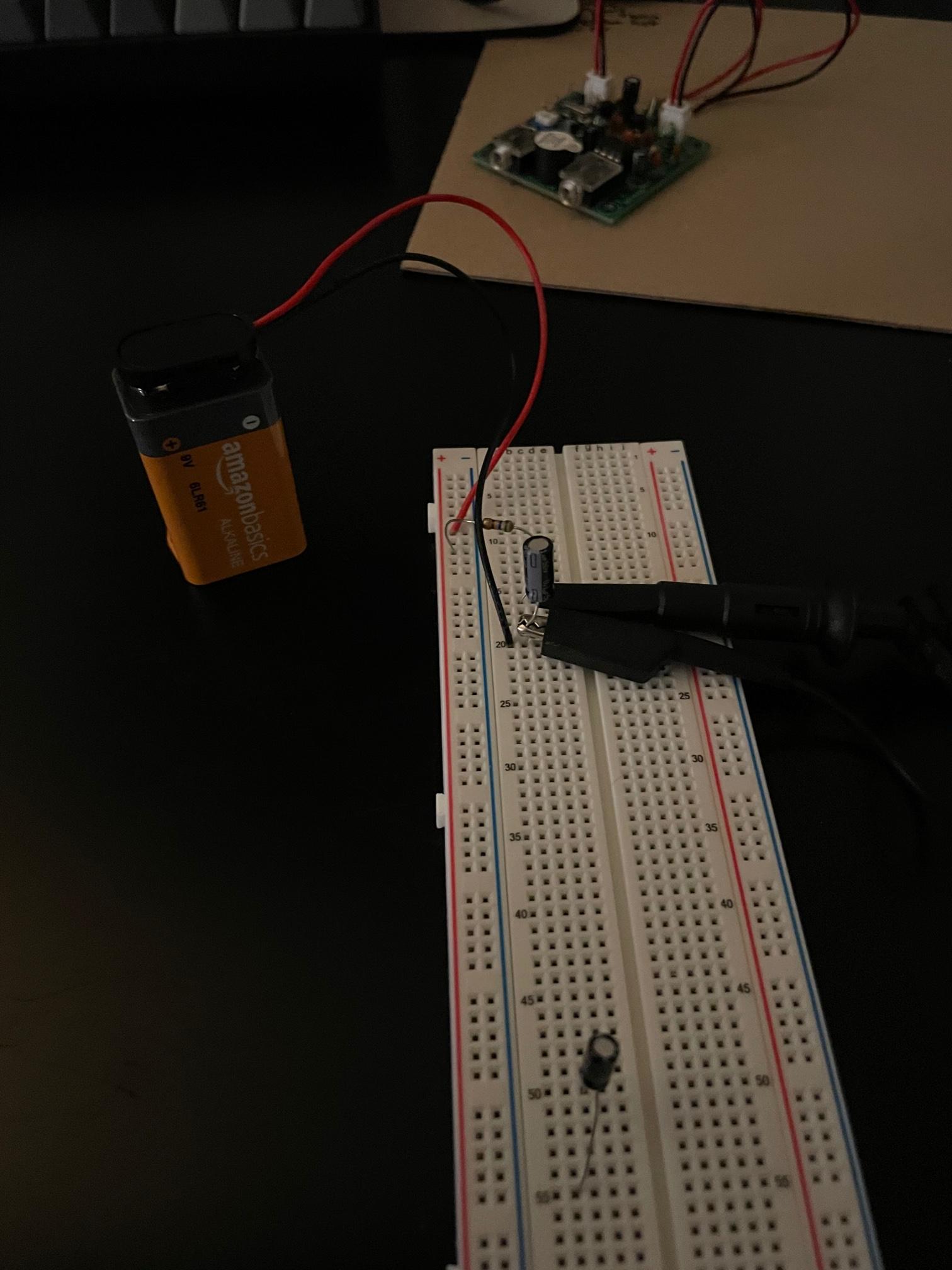
For some reason it shows what looks to be like a capacitor charging if I am not mistaken.

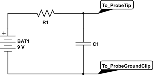
Here is the picture of the circuit:

Picture of the simulation: enter image description here

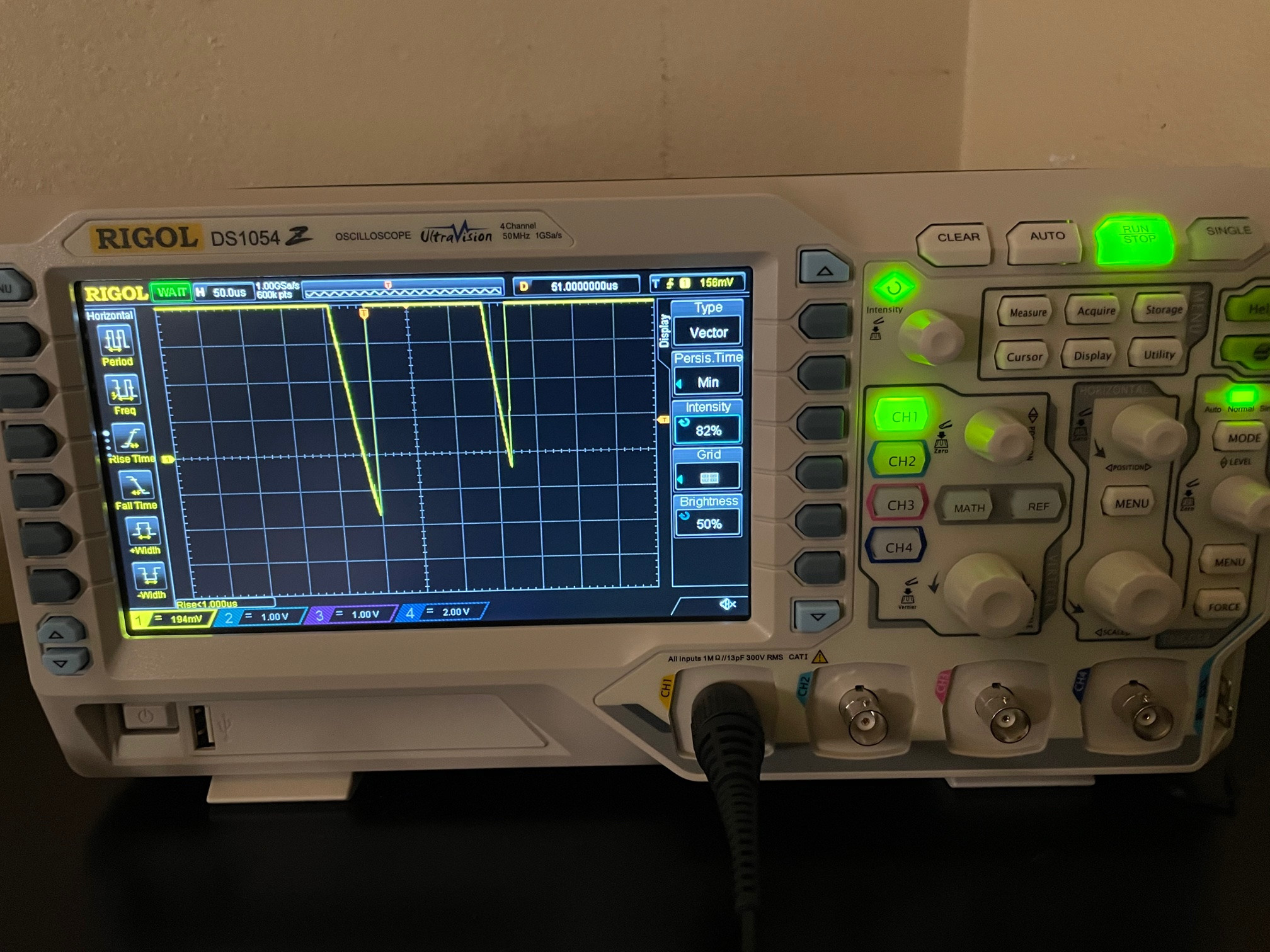
Trying to reproduce the results I get this:

\$\endgroup\$
1
  • \$\begingroup\$ [Incidentally, if you put a FAT32-format USB flash drive in the USB socket, you can press the oscilloscope button with a printer icon to save a screen grab to the drive.] \$\endgroup\$ Commented Dec 26, 2020 at 16:00

2 Answers 2

3
\$\begingroup\$

You can, and you did.

Largely this was possible because you used storage scope.

If you had only an analog scope available, then to keep an image on the screen you would have likely needed to repeat the same experiment over and over, alternately charging and discharging the capacitor using a square wave source.

You also appear to have chosen a small enough resistor that the RC time constant was brief enough to accomplish a full charge during the first tentative contact you (manually?) made. It's quite possible that first tentative contact did not last but rather "bounced" however your scope sweep is so fast that your entire charging process may have occurred between the first tentative contact and any temporary disconnect, as there seems to be no "hesitation" in the charging curve.

And you selected a trigger which well captured the event of interest.
\$\endgroup\$
4
  • \$\begingroup\$ Yes, I chose a 0.1µF capacitor. I am only confused because I am having trouble replicating what I just did. I got an oscilloscope because our University is fully online and they gave us this crappy data acquisition device where you download a program and you get all the necessary tools like a function generator, oscilloscope DMM, etc from the program. We can't go into our laboratories, and I rather learn this material on a real oscilloscope. So sorry for any amateur questions in advance. \$\endgroup\$ Commented Dec 26, 2020 at 6:46
  • \$\begingroup\$ There are super cheap function generator kits, you could also use an Arduino. Your scope even has a weak output on the front panel for probe compensation though you should not perhaps load it, especially not with an already charged capacitor. Use a larger resistor and capacitor and a free running trigger mode and you can probably watch the voltage rise in human time. \$\endgroup\$ Commented Dec 26, 2020 at 6:56
  • \$\begingroup\$ Okay, I'll look into it. I'll try that too. \$\endgroup\$ Commented Dec 26, 2020 at 7:04
  • \$\begingroup\$ Ah - I got it. So I am able to reproduce the results again. I let the capacitor discharge, when unplugged. Then re-plugging the 9V in I am able to recharge the capacitor, which gives me the result. \$\endgroup\$ Commented Dec 26, 2020 at 7:18
2
\$\begingroup\$

My question is can I just use my oscilloscope to measure the voltage across a capacitor

Of course, you can.

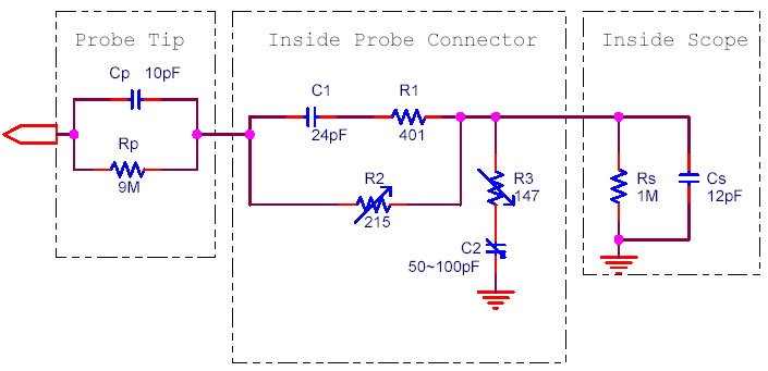
But there's one thing to consider: There's a circuit consisting of passive elements inside the scope's probe. And, in your circuit, you are loading the capacitor with those elements. So the measurement can be affected by these elements.

Your circuit looks like this:

schematic

simulate this circuit – Schematic created using CircuitLab

And a 10:1 scope probe's circuit looks like this: enter image description here Img Src

I can't see the values from the photo and I can't even make a guess. But I should say that if R1 in your circuit is too large (i.e. in MegaOhms range) then the measurement can be inaccurate as the resistors inside the probe circuit form a divider with R1.

\$\endgroup\$
5
  • 2
    \$\begingroup\$ You can see the short timescale and the sort of capacitor used, from which it's straightforward to determine that the charging resistance cannot be very high. While the effect you mention is real, it may well be smaller than can be seen with the limited amplitude resolution of that scope. \$\endgroup\$ Commented Dec 26, 2020 at 6:45
  • \$\begingroup\$ It is a 560Ω resistor, which is rather small, and a capacitor value of 0.1µF. \$\endgroup\$ Commented Dec 26, 2020 at 6:49
  • \$\begingroup\$ @GenoC no problem then. What I say is a generalized thing just to consider, when you want to try something different tomorrow. \$\endgroup\$ Commented Dec 26, 2020 at 6:52
  • \$\begingroup\$ Yeah no, thank you I appreciate it! This is very helpful. \$\endgroup\$ Commented Dec 26, 2020 at 6:58
  • \$\begingroup\$ @ChrisStratton yeah, you are right. Looking at the oscillogram is not the first thing that came to my mind :) Thanks anyway. \$\endgroup\$ Commented Dec 26, 2020 at 7:04

Your Answer

By clicking “Post Your Answer”, you agree to our terms of service and acknowledge you have read our privacy policy.

Not the answer you're looking for? Browse other questions tagged or ask your own question.