0
\$\begingroup\$

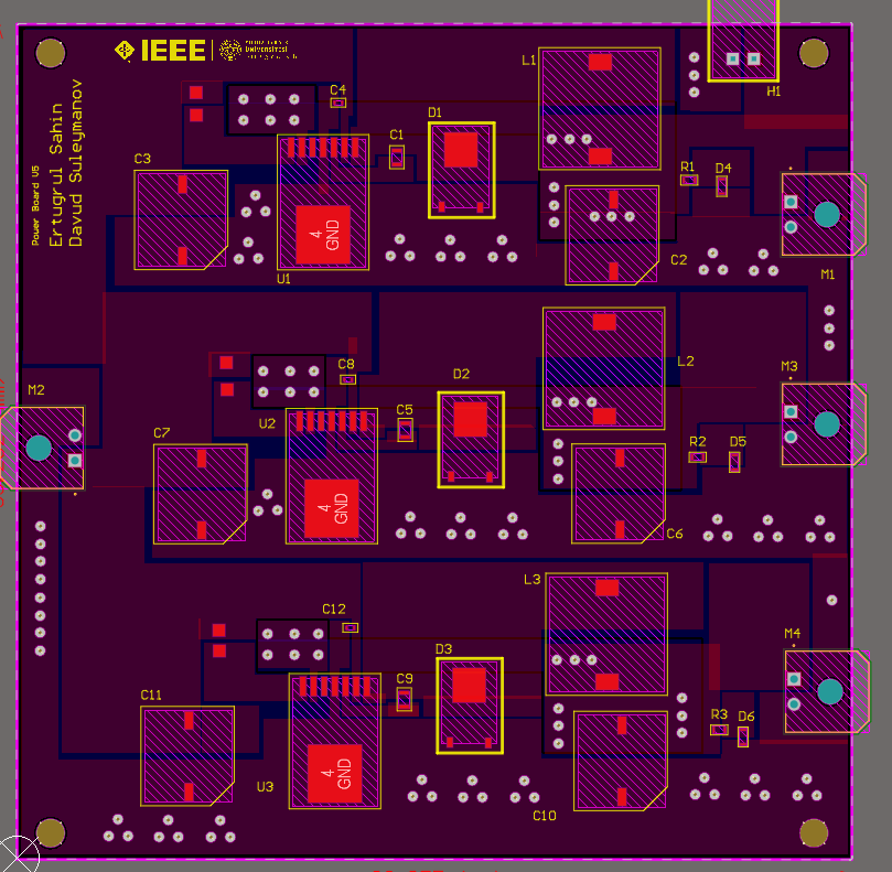
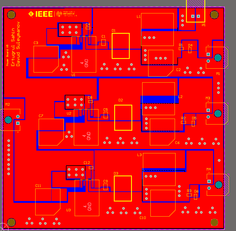
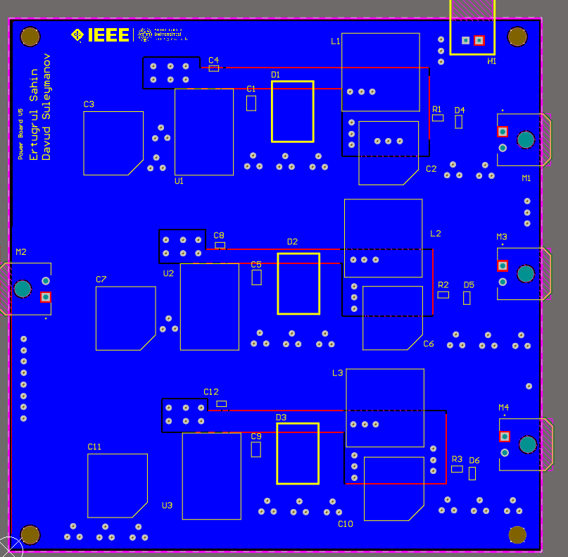
PCB:

enter image description here

enter image description here

enter image description here

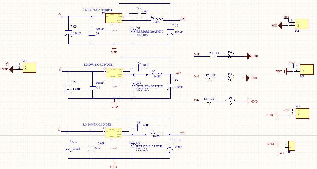
My name is Ertuğrul. I made a regulation board with an LM2678 but I have a problem: I provide 12V input but I can not get 5V output.

I only get 5V with the on/off pin enabled, but the datasheet says that I can get a 5V output with the on/off pin not active.

I have to give 1.4-6V to the on/off pin because otherwise it does not work.

I tried it on a breadboard but it did not change. I used Webench schematic design.

Do you know about LM2678? Can you help me ?

enter image description here

\$\endgroup\$
4
  • \$\begingroup\$ You're right, you should be able to leave the ON/OFF pin not connected. Where did you source the parts? Are you sure they're genuine ? Perhaps add a picture of the PCB, there might be an error that you overlooked. \$\endgroup\$ Commented Dec 28, 2020 at 21:20
  • \$\begingroup\$ Nothing to do with the problem, but I would change your diode symbol from Zener to Schottky. I had to go look the part up to verify it was a Schottky. \$\endgroup\$
    – GB - AE7OO
    Commented Dec 29, 2020 at 7:20
  • \$\begingroup\$ I add new picture about my pcb.Also my diode is schottky.I made this circuit on breadboard.the result did not change \$\endgroup\$ Commented Dec 29, 2020 at 11:28
  • \$\begingroup\$ Your layout is not optimal. You have a big loop in your input capacitors (e.g. C3 and C4). The leads of C3 and C4 must be connected to the input pins as short as possible. This could cause the regulator to behave strange. You might want to follow the layout of the official LM2678 eval board. \$\endgroup\$ Commented Dec 29, 2020 at 12:44

0

Your Answer

By clicking “Post Your Answer”, you agree to our terms of service and acknowledge you have read our privacy policy.