0
\$\begingroup\$

I am in need of a constant voltage regulator to power my motors, as voltage will affect the motors' RPM. Although I could compensate via software, I would like to add a hardware deterrence.

My setup would be:

  • A 7.4 V nominal supply. This is from two 18350 li-ions so 8.4 V at full charge and 6.8 V
  • Four separate motors that at peak efficiency consume 0.5 A at 7 V

My target features are

  • Output current of 1 A to 2 A (I could always use 2 or 4 if need be, of the same circuit)
  • Can output a voltage of at least 6 - 9 V
  • Can be made using SMD components :)
  • Most importantly: a cut-off voltage

I have seen a good one from Pololu here but I am going to do a single-board circuit. I have tried looking at what IC Pololu is using but I could not find it (I also doubt they will tell me.) I also tried searching, but I am quite overwhelmed by the extra specs manufacturer give (frequency, Iq, etc.) and don't know which one is for me.

I guess this question boils down to - can you recomend a good buck-boost converter IC that fits my needs and has decent documentation that contains a sample circuit in order for me to create?

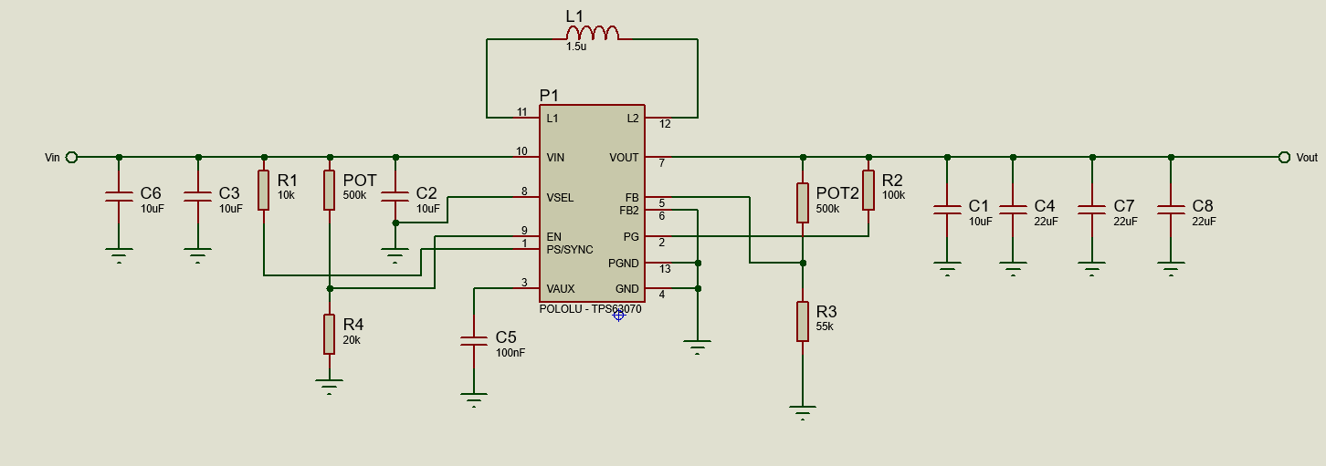
Edit: Based on the chip and with the help of The Photon, I have made this circuit:

enter image description here

\$\endgroup\$
3
  • \$\begingroup\$ a zener, an opamp, and a fet should take care of you, no need for an IC \$\endgroup\$
    – dandavis
    Commented Aug 21, 2019 at 20:46
  • \$\begingroup\$ oh really can you show some example circuits? to be honest with you i am not good at using op-amps that why i tend to rely on ready made IC \$\endgroup\$
    – Jake quin
    Commented Aug 21, 2019 at 20:50
  • \$\begingroup\$ @ThePhoton would you like to post that as an answer? i will look into it, it might take me some time to tell you if i will go with that IC \$\endgroup\$
    – Jake quin
    Commented Aug 21, 2019 at 20:51

1 Answer 1

1
\$\begingroup\$

I have seen a good one from pololu here but i going to do a single board circuit. I have tried looking for what IC pololu is using but i could not find it (i also doubt that they will tell me).

FWIW, it looks like they're using TPS63070.

It matches the Pololu description in several points:

  • Marked with "3070" like the device pictured on the Pololu website

  • Comes in a 2.5 x 3 mm QFN-like package

  • user defined under-voltage lockout

  • 2 - 16 V input range

  • Unusual pin arrangement with 3 pins along one edge with 4 pins on the opposite edge

\$\endgroup\$
21
  • \$\begingroup\$ Thank you very much, May i ask. What do you mean by switch current? Is this the output current. And what am i expecting from the output of the buck-boost is it already a clean dc , or i still have to filter it out myself? \$\endgroup\$
    – Jake quin
    Commented Aug 21, 2019 at 21:04
  • \$\begingroup\$ @Jake, that's the maximum current the switch inside the IC can carry. It will be the same as the inductor current. The rating has to be higher than the average output current because the inductor (and switch) current oscillates around the average current. \$\endgroup\$
    – The Photon
    Commented Aug 21, 2019 at 21:08
  • \$\begingroup\$ I see kinda misleading for beginners, Thank you for pointing that out \$\endgroup\$
    – Jake quin
    Commented Aug 21, 2019 at 21:13
  • \$\begingroup\$ Also last question is it a good idea to place this near to each other? will the inductor not affect the other inductor? with this specs i might have to use 2 of them \$\endgroup\$
    – Jake quin
    Commented Aug 21, 2019 at 21:16
  • \$\begingroup\$ Place what near each other? What other inductor? It will depend what kind of inductors you choose. \$\endgroup\$
    – The Photon
    Commented Aug 21, 2019 at 21:20

Your Answer

By clicking “Post Your Answer”, you agree to our terms of service and acknowledge you have read our privacy policy.

Not the answer you're looking for? Browse other questions tagged or ask your own question.