0
\$\begingroup\$

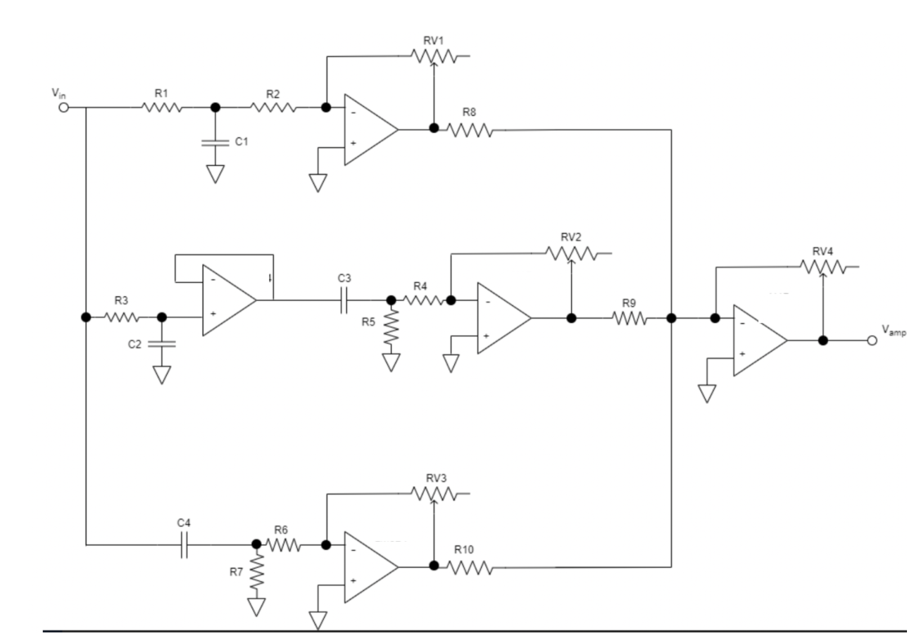
For a personal project I was designing a basic audio equalizer circuit using this online simulation tool called TinkerCad.

I managed to build the circuit but for some reason I really can't get it to work.

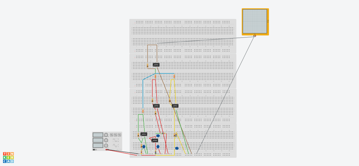
I think it has to do with the fact I connected multiple breadboards and I may not have connected them properly (I had to do this because you cannot shorten the lengths of resistors on TinkerCad.)

Attached below are the screenshots of the circuit diagram, and a snapshot of the breadboard.
enter image description here

enter image description here

\$\endgroup\$
12
  • 1
    \$\begingroup\$ So how does it not work? How have you debugged what is wrong? Which op amp are you using? But have you even connected power supplies to the opamps? \$\endgroup\$
    – Justme
    Commented Jan 8, 2021 at 17:51
  • \$\begingroup\$ hm, I think if you need multiple breadboards, you've simply long outgrown tinkercad. Why transform your perfectly fine schematic into a "would never actually build this on breadboard if the simulation is working" work-intense tinkercad simulation? Just transfer your circuit into any of the free SPICE simulators, and do a proper simulation. \$\endgroup\$ Commented Jan 8, 2021 at 17:52
  • \$\begingroup\$ Honestly, I did it on spice it works perfectly fine but for the project I'm required to run it on tinkercad. \$\endgroup\$ Commented Jan 8, 2021 at 17:53
  • \$\begingroup\$ @Justme, do I still need to supply power to the op amps? and also the simulation does not work at all. \$\endgroup\$ Commented Jan 8, 2021 at 17:53
  • \$\begingroup\$ @KarryAlams Do you think electronics work without power supply? That might be the reason why the simulation does not work. Or then simulation simplifies the power supply and it is implicit in the simulation. But still, which op-amp model you are using? And can you describe in which way the simulation does not work at all? What component values did you use? And why is Tinkercad required - is this school project or homework? \$\endgroup\$
    – Justme
    Commented Jan 8, 2021 at 17:55

3 Answers 3

1
\$\begingroup\$

The simulation does not work because the op-amp power supply pins are not connected to a power supply.

\$\endgroup\$
1
\$\begingroup\$

using Tinkercad has no relevance really to how you build your prototype. Figure out how to build your prototype on breadboard or stripboard with the components reasonably close together. Read up on power supply wiring and decoupling, you will need this to get things working properly. You also need a good solid ground to all parts of your circuit.

What you are doing is actually both commendable and very educational, many people never go beyond simulation to actually trying to build a real circuit. When you do make a real physical circuit, all kinds of things start to become important which are not really a big deal in the "ideal conditions" of simulation. This starts with grounding and power supplies. You might encounter some frustration but you will learn if you persist. Also you will likely find it helpful to have coupling caps of 10uF or so at input and output of your circuit (to remove DC).

\$\endgroup\$
0
\$\begingroup\$

Change all the DC grounds on Op Amps and resistors to Vcc/2 with 2 R’s with unity gain buffer for a single supply. Add cap.

\$\endgroup\$

Your Answer

By clicking “Post Your Answer”, you agree to our terms of service and acknowledge you have read our privacy policy.

Not the answer you're looking for? Browse other questions tagged or ask your own question.