0
\$\begingroup\$

I have a STM32F051R8 (STM32F0 discovery board) I am trying to use to generate a PWM using a timer and change the pulse width at runtime. My code is:

// configuration
  htim1.Instance = TIM1;
  htim1.Init.Prescaler = 0;
  htim1.Init.CounterMode = TIM_COUNTERMODE_UP;
  htim1.Init.Period = 65535;
  htim1.Init.ClockDivision = TIM_CLOCKDIVISION_DIV1;
  htim1.Init.RepetitionCounter = 0;
  htim1.Init.AutoReloadPreload = TIM_AUTORELOAD_PRELOAD_DISABLE;

// runtime
  if(HAL_GPIO_ReadPin (GPIOA, B1_Pin)) {
    // Set The LED ON!
    HAL_GPIO_WritePin(GPIOC, LD4_Pin, GPIO_PIN_SET);
    HAL_GPIO_WritePin(GPIOC, LD3_Pin, GPIO_PIN_RESET);
    __HAL_TIM_SET_COMPARE(&htim1, TIM_CHANNEL_1, 750);
    htim1.Instance->CCR1 = 65534/2;
  } else {
    // Else .. Turn LED OFF!
    HAL_GPIO_WritePin(GPIOC, LD3_Pin, GPIO_PIN_SET);
    HAL_GPIO_WritePin(GPIOC, LD4_Pin, GPIO_PIN_RESET);
    __HAL_TIM_SET_COMPARE(&htim1, TIM_CHANNEL_1, 500);
    htim1.Instance->CCR1 = 65534/4;
  }

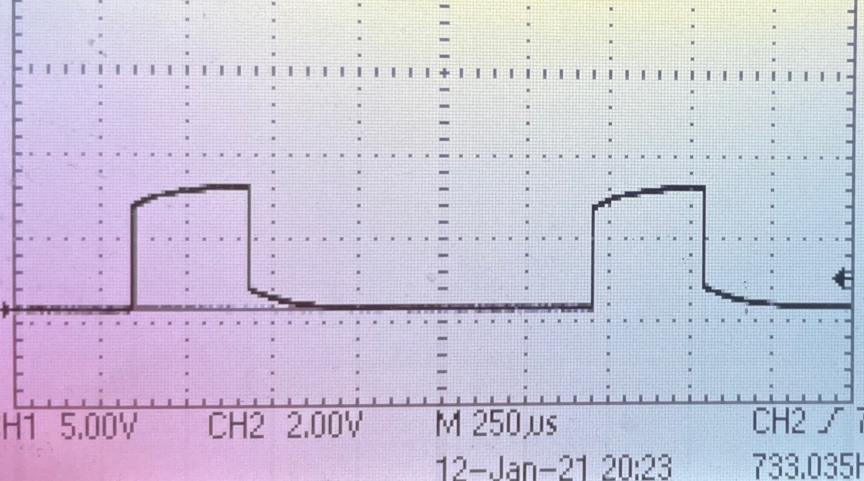
My problem is the signal looks like this:

pwm problem

Why are the waves like that? I thought they were supposed to be square. Am I doing something wrong, or is there some kind of setting I must apply?

\$\endgroup\$
4
  • 5
    \$\begingroup\$ Check the compensation on your oscilloscope probes first. Your scope should have a calibration signal output. Check that it shows a nice square wave. If not, adjust the compensation screw on your probe to get the square wave square. Check your PWM again after that. \$\endgroup\$
    – JRE
    Commented Jan 12, 2021 at 11:18
  • 1
    \$\begingroup\$ Which pin is that? How is it configured? Does it have anything else connected? Is the scope probe a 10x one or switchable and set to 10x mode and properly compensated? \$\endgroup\$
    – Justme
    Commented Jan 12, 2021 at 11:20
  • \$\begingroup\$ Checking the scope now; it's the PA8 pin with nothing else connected. \$\endgroup\$
    – Nick M
    Commented Jan 12, 2021 at 11:26
  • \$\begingroup\$ Indeed it was the scope! Thank you very much! \$\endgroup\$
    – Nick M
    Commented Jan 12, 2021 at 11:28

1 Answer 1

2
\$\begingroup\$

That looks very much like a problem with the compensation adjustment on your probes.

Your scope should have a calibration signal output. Check that your scope shows a nice square wave when the probe is connected to the calibration output.

If the calibrstion output doesn't look nice and square with straight, vertical edges and flat, horizontal tops and bottoms, adjust the compensation screw on your probe to get the square wave square.


A digital output from a microprocessor should normally have straight edges and a flat top and bottom. If it doesn't then you either have too much of a load on it or the scope (probes) need to be adjusted.

\$\endgroup\$
1
  • \$\begingroup\$ Thank you, it worked! \$\endgroup\$
    – Nick M
    Commented Jan 12, 2021 at 11:52

Your Answer

By clicking “Post Your Answer”, you agree to our terms of service and acknowledge you have read our privacy policy.

Not the answer you're looking for? Browse other questions tagged or ask your own question.