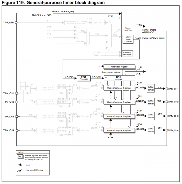
There is no concept of connecting interrupts each other. You need to connect timers in master & slave configuration.
See MMS (Master Mode Selection) bits of TIMx_CR2 register. These must be set to 0b010 (Update), so that the master timer creates a pulse on TRGO (Trigger output) whenever it overflows, in other words, after each PWM pulse it generates. I assume you have made the other settings correctly for the master timer to produce a PWM. Do not enable interrupts for master timer.
In the slave timer, see SMS (Slave Mode Selection) and TS (Trigger Selection) bits in TIMx_SMCR register. SMS must be 0b111 (External clock mode 1). And you must also set TS bits according to the master timer you use, which must be one of the ITRx options.
Slave timer needs a prescaler of 1 (TIMx_PSC = 0). Set the TIMx_ARR register according to the desired pulse count and enable update interrupt of the slave timer. Slave timer interrupt should be triggered when the desired pulse count is reached. And in the slave timer interrupt service routine, you can stop the master timer.
I haven't recently tested these steps and I'm not sure if I missed something or not, but I believe they can put you in the right direction.

