0
\$\begingroup\$

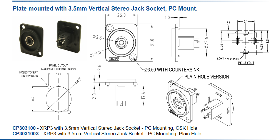
I was shopping for some aux connectors and when I found one that should suit my purpose I checked the data sheet. Now I am unsure how I can figure out which pin on the part does what.

I looked at some other data sheets and was unable to find which pins do what.

Here my question, how do I find out which pin on the part is for example used for ground?

Here is the data sheet of one of the aux connectors I was looking at. Here is the link to the data sheet: https://www.farnell.com/datasheets/3164267.pdf

enter image description here

\$\endgroup\$
0

4 Answers 4

2
\$\begingroup\$

The data sheet extract you have shown gives pin numbers but no diagram of the pin functions. Examination of the remainder of the datasheet doesn't reveal any further information.

Your best option is to insert a 3.5 mm stereo jack into the socket and determine the pinout by continuity test.

enter image description here enter image description here

Figure 1 and 2. From here.

Since there are four terminals there may be a mic contact (4-pole connector in Figure 1) or a switch contact that closes to indicate that the plug has been removed (a cut-down version of Figure 2). You can determine this by continuity test also.

I think it might be worthwhile to point out to them that their datasheet is lacking some basic information. I was buying their jack plugs and sockets over 40 years ago so they're on the go a long time and have some reputation to maintain.

\$\endgroup\$
0
\$\begingroup\$

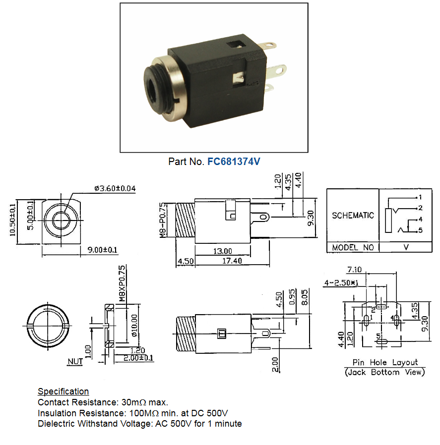
Okay, so the datasheet there is for an assembly containing a jack with a different part number. If you follow the part number(s) for that jack.. well unlike the other ones on that page you'll not find one. Searching the manufacturer for a similar name, we find this

enter image description here

Which appears to be correct, but if I were you, I'd request clarification from the manufacturer or test a sample yourself.

This kind of thing is not uncommon with connector datasheets, which tend to emphasize the mechanical features at the expense of the electrical characteristics.

\$\endgroup\$
0
\$\begingroup\$

Unless they are explicitly marked, this is application dependent. You can choose whichever pin you want, for whichever function you want. Usually they will give ratings for each pin, and unless a pin is connected to a metal housing they won't identify ground.

If you are replacing a connector in an existing application, you will need to determine which pin does what, the pin locations at the back of the connector are not usually standard, so you can't always just follow the pattern even if they look the same.

\$\endgroup\$
0
\$\begingroup\$

You linked to a plate that supports many connectors such as the 6.35mm or 1/4” jack. The 3 solder tabs correspond with the same contacts on the plug.

The 4th is a contact switch for gnd to detect insertion. If in doubt, ask supplier or ohm out a sample.

The PCB contacts are for mechanical support.

The body solder rings are for wires.

https://www.cliffuk.co.uk/products/jacksockets/s2.htm

\$\endgroup\$

Your Answer

By clicking “Post Your Answer”, you agree to our terms of service and acknowledge you have read our privacy policy.

Not the answer you're looking for? Browse other questions tagged or ask your own question.