2
\$\begingroup\$

I'm looking to create a simple circuit to connect/disconnect a power storage capacitor to/from a larger circuit. In the model railroading world, we use capacitors as "keep-alives" to keep the decoder (the larger circuit mentioned above) powered when a train rolls over dirty track or a dead spot. This can create a problem when programming the decoder. The programming process requires removing power from the decoder for periods of time, and if the capacitor is connected during this process, programming can fail.

The decoders I use have a logic level (4.5V) output that is active high when the capacitor (~12V) can be connected to the decoder, low when the capacitor should be disconnected. I've seen others use this signal to control a FET that controls a solid state relay that connects and disconnects the capacitor, but SSRs are (relatively) expensive and this seems like something that should have a single IC solution to me. I was thinking this could probably be done with a power MOSFET, not remembering that MOSFETs are unidirectional devices (since the capacitor is both charged and discharged by this circuit).

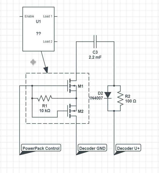
I found that two MOSFETs can be used back-to-back to create a bidirectional "switch", so I ordered a few QS5K2TR common source 2 channel N-FETs to play around with. I have gotten this approach to work on my bench by connecting drain 1 to ground and drain 2 to the negative side of the capacitor and controlling the gates by connecting them to +5V or leaving them floating. For this to work, I had to connect the shared Source to the gate through a 10K ohm resistor, similar to what is found here: https://www.homemade-circuits.com/bidirectional-switch. I haven't seemed to need the charge pump mentioned when using back-to-back N-FETs.

Here's the circuit as it stands:

Capacitor Power Pack

I'm a bit uncomfortable with this solution since I don't really understand why the shared Source needs to be connected to the gate through the resistor. (Well, I understand that N-FETs rely on Vgs to turn on/off, but I would think that connecting the shared Source to Gate through a resistor would prevent this from working correctly, especially since the "high" voltage current of charging or discharging the capacitor flows through this shared Source)

I also haven't been able to find what seems like the usual solution for what I have to imagine is a rather common problem: disconnecting a battery/capacitor that is charged and drained over the same lines. I'm sure this is because I'm not using the right search terms.

Can anybody point me towards the correct approach for this problem? Is there a single IC that could fill the roll of U1 above, replacing the dashed box?

Thanks for your help!

\$\endgroup\$
4
  • 1
    \$\begingroup\$ To better express and annotate the circuits you describe as well as your doubts, can you include schematics? While words may seem unambiguous when you write them, sometimes they can lead to subtle confusion or errors of interpretation. \$\endgroup\$
    – nanofarad
    Commented Apr 8, 2021 at 16:40
  • \$\begingroup\$ Schematic added! \$\endgroup\$
    – uknowit90
    Commented Apr 8, 2021 at 16:50
  • \$\begingroup\$ I was able to determine that this circuit only works if the PowerPack Control switches between +4.5V and floating. The actual control circuit will switch between +4.5V and Ground, and when the fets' gates are connected to ground in this circuit, they turn back on :( \$\endgroup\$
    – uknowit90
    Commented Apr 10, 2021 at 4:44
  • \$\begingroup\$ @uknowit90 - you need to float the gate when disabled because any current drawn from the U+ supply will cause the voltage across the FET pair to go negative. This then requires that the gate go negative (or float) to prevent it from turning on. \$\endgroup\$ Commented Apr 10, 2021 at 21:02

1 Answer 1

1
\$\begingroup\$

Common terminology for such devices is "load switch"

For example NCP3902 Load bidirectional load switch

For this particular application, it doesn't seem that you need a bidirectional switch as the main requirement is to be able to stop the capacitor from discharging into the load when the logic signal is low. It is probably acceptable if the capacitor charges if the 12V supply is above the voltage of the capacitor even if the control signal is low.

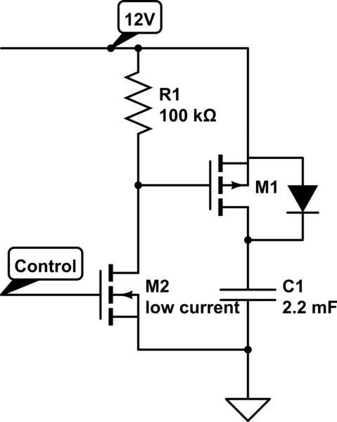
This can be achieved with a single P-channel FET arranged as a high-side switch. There will be a small discharge current from the 12v rail when the capacitor is turned on, but none when off.

schematic

simulate this circuit – Schematic created using CircuitLab

\$\endgroup\$
1
  • \$\begingroup\$ Unfortunately, I don't have a reflow oven, so that particular part is a no go. I've searched for a similar option, but I can't find anything that is 1) bi-directional, 2) hand solderable, and 3) capable of controlling 12V+. I did find that I could use mosfet driver to control the back-to-back mosfets (bristolwatch.com/ele3/2c.htm), but this is effectively the same as creating my own solid state relay, and the LED in the driver exceeds the current the logic level pin can on the decoder can supply. I might as well use a real solid state relay and a mosfet to control it. \$\endgroup\$
    – uknowit90
    Commented Apr 10, 2021 at 4:43

Your Answer

By clicking “Post Your Answer”, you agree to our terms of service and acknowledge you have read our privacy policy.

Not the answer you're looking for? Browse other questions tagged or ask your own question.