0
\$\begingroup\$

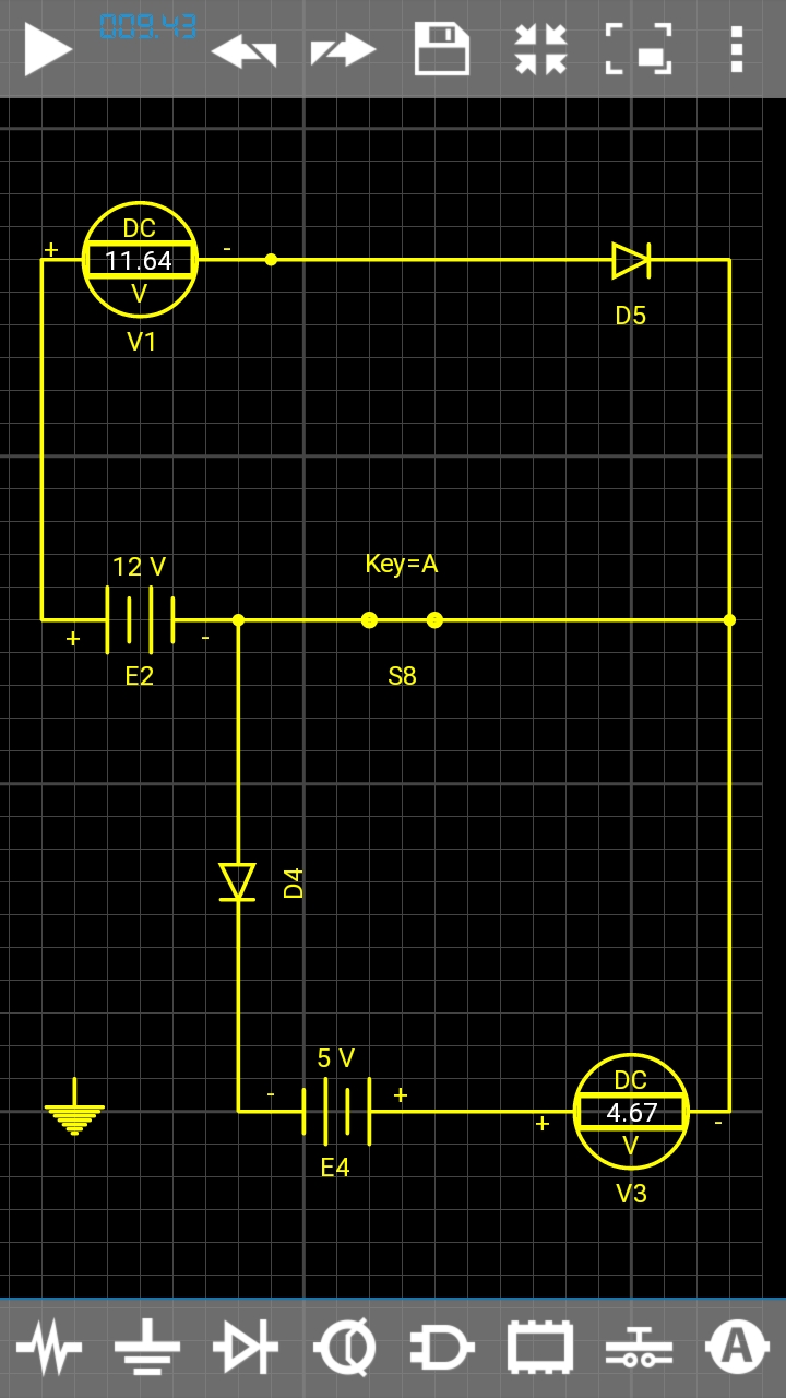
I have 2 DC sources 12V and 5V, I want to switch them using one switch as shown on scheme. I used here 2 diodes to isolate circuits and it works fine on simulation, but in real scheme 5V (actually rather 4.7V from USB) becomes 5.4V. How can I make circuits run independent (ie. they do not affect each other) in this case?

enter image description here

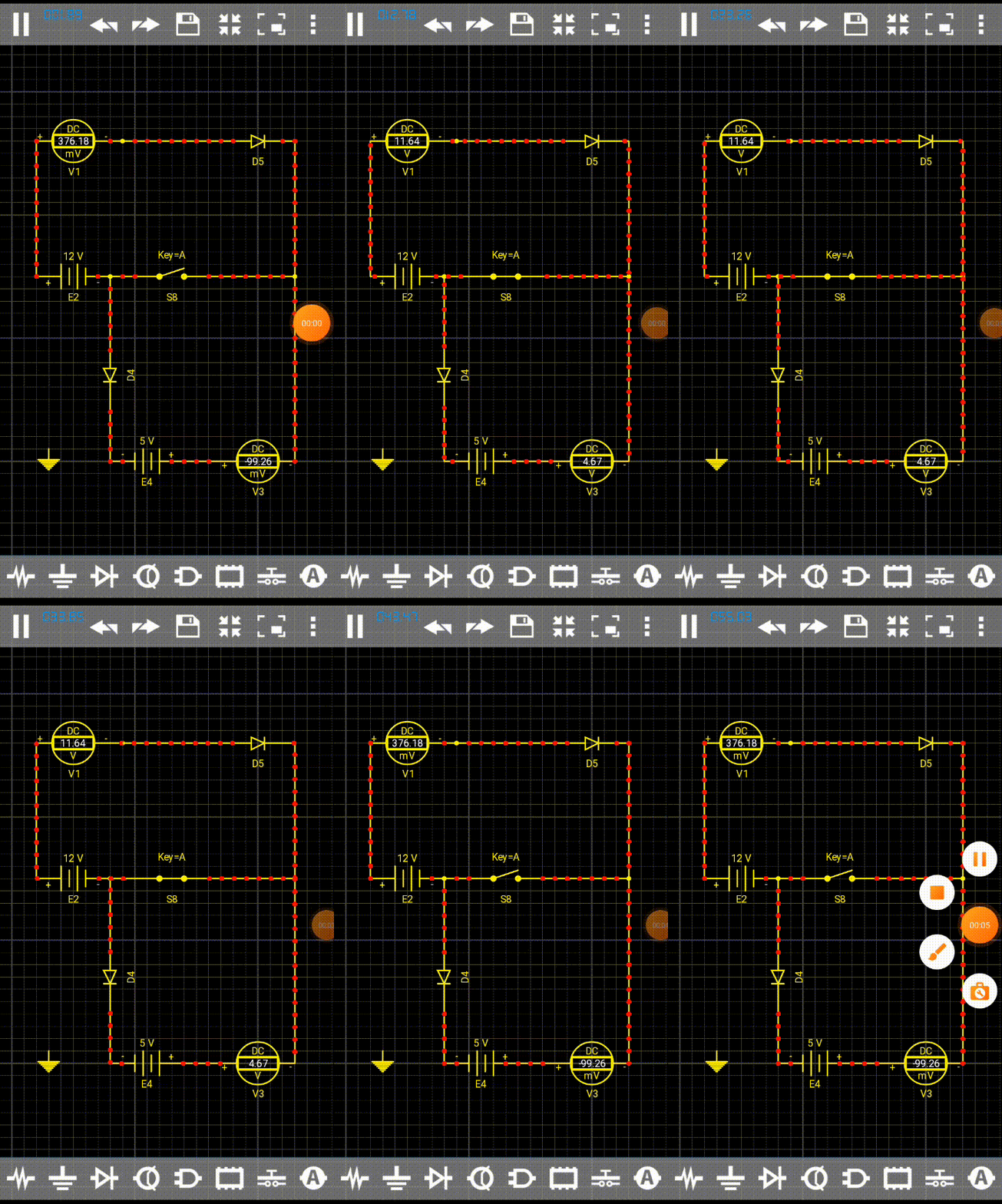
Simulation with open/closed switch - works fine on simulation but not in reality

enter image description here

\$\endgroup\$
2
  • 2
    \$\begingroup\$ Why not simply use a DPST switch? \$\endgroup\$ Commented Apr 24, 2021 at 18:50
  • \$\begingroup\$ @Unimportant yeah it's a good point, but in real schema I have an SPDT Centre Off with an another circuit on the second switch position, so I have to bind these two circuits on the remaining position \$\endgroup\$
    – schmidt9
    Commented Apr 24, 2021 at 19:13

2 Answers 2

2
\$\begingroup\$

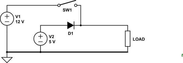
schematic

simulate this circuit – Schematic created using CircuitLab

Figure 1. Using a single-pole normally-open switch to select '5 V' or 12 V supply.

  • SW1 open: 5 V is supplied to the load via D1. A silicon diode will drop 0.7 V. A Schottky diode will drop about 0.3 V.
  • SW1 closed: 12 V is supplied to the load. D1 prevents backfeed into the 5 V power supply.

schematic

simulate this circuit

Figure 2. Switch to disconnect two loads.

  • SW1 will disconnect the common return from both loads to the common ground at the power supplies.
  • D1 prevents V1 back-feeding into V2 when SW1 is open. It will cause a voltage drop in normal operation as described above.

This isn't an elegant circuit. Switching negatives in a negative ground circuit can lead to all sorts of confusion. It is, however, common on automobile circuits.

\$\endgroup\$
5
  • \$\begingroup\$ Sorry if I was unclear - 2 circuits have 2 different loads, they should run simultaneously not in turn if the switch is closed and stop if the switch is open \$\endgroup\$
    – schmidt9
    Commented Apr 24, 2021 at 18:25
  • \$\begingroup\$ Loads are represented here by 2 voltmeters \$\endgroup\$
    – schmidt9
    Commented Apr 24, 2021 at 18:33
  • \$\begingroup\$ Are the sources battery or regulators? Can the 5 V regulator be fed from the 12 V source? \$\endgroup\$
    – Transistor
    Commented Apr 24, 2021 at 18:39
  • \$\begingroup\$ Sources are 2 batteries here, please see I added Gif picture \$\endgroup\$
    – schmidt9
    Commented Apr 24, 2021 at 18:42
  • 1
    \$\begingroup\$ See the update. See also how I've drawn the schematic with higher voltages at the top so that current flows from top to bottom and circuit reads naturally from left to right. See rules-and-guidelines-for-drawing-good-schematics if you're interested in improving. \$\endgroup\$
    – Transistor
    Commented Apr 24, 2021 at 18:46
1
\$\begingroup\$

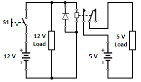
Here's how, with the switch 'S1' being used to control the 12 V load and a 12 V electromagnetic relay to control the 5 V load.

enter image description here

\$\endgroup\$

Your Answer

By clicking “Post Your Answer”, you agree to our terms of service and acknowledge you have read our privacy policy.

Not the answer you're looking for? Browse other questions tagged or ask your own question.