0
\$\begingroup\$

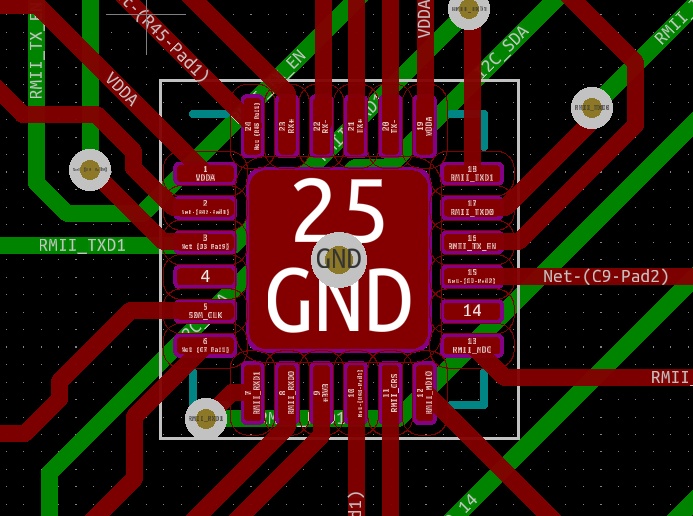
On my board I have an LAN8720AI QFN24 package. When I route it via FreeRouting I get this:

QFN24

As you can see most pins are routed fine but some like pin 18 (RMII_TXD1) just goes straight up instead of right and up. As this is my first bigger design with a smaller microcontroller I was wondering if that is actually all right to do or if I should change that myself to make it look a bit better.

\$\endgroup\$
2
  • \$\begingroup\$ Don’t use an autorouter! You are much better off routing manually. Is there a groundplane in your design? I think Olimex has a design using an ESP32 with ethernet - you might be able to use that as an example. \$\endgroup\$
    – Kartman
    Commented May 17, 2021 at 22:20
  • \$\begingroup\$ I think the Autorouter does a better job as I dont have any idea on how to route effectively ones the routes start to be that complex as they are right now. Yes I use the design from olimex but they use a lan8710 but there is still a Wesp32 and someone on youtube made a esp32 with lan but the layout is not online only the schematic. \$\endgroup\$
    – Daniel Do
    Commented May 18, 2021 at 7:06

3 Answers 3

1
\$\begingroup\$

This is perfectly fine. Since there's solder mask on top of that trace, you won't get any problems when soldering the chip. Of course, if you want to make it nicer, you can - but there's no technical reason to do so.

Be careful with that ground via in the middle ground pad though, it might suck away all of the solder that's supposed to stay on the pad. You might want to use multiple smaller vias (the smallest you can get) instead.

You might also want to get the via next to pin 7 a bit further away from the chip for the same reason (solder wicking into the via).

\$\endgroup\$
3
\$\begingroup\$

I would be more concerned about crosstalk of differential signals being unbalanced or following different paths rather than following the same path on opposing layers, and noise decoupling on Vdd/Vss and Agnd.

\$\endgroup\$
2
  • \$\begingroup\$ Oh, seems I put the decouplers to far away. They are there but not much of a sense if I look at it now. Thanks! What do you mean about crosstalks and unbalance ? Seems I need to fix that on my own as the freerouter is fairly "stupid" \$\endgroup\$
    – Daniel Do
    Commented May 17, 2021 at 14:56
  • \$\begingroup\$ electronics.stackexchange.com/questions/423824/… \$\endgroup\$
    – D.A.S.
    Commented May 17, 2021 at 15:14
1
\$\begingroup\$

Pin 18 is fine but I don't see bypass caps on the supply lines close to the chip.

I assume you're using an external oscillator rather than a crystal- the XTAL1 pin routing is also sensitive.

\$\endgroup\$
2
  • \$\begingroup\$ Oh thanks, I missed that one ! Yes. I am using a external 50MHz osc. that gets connected to a ESP32. Because of that I had to use "farther" lines about 52,8mm. I tried to make the connection to every signal length the same. I.e from every pin to another with the clock signal is 52,8mm without any 90° edges if that is what you mean, \$\endgroup\$
    – Daniel Do
    Commented May 17, 2021 at 14:55
  • \$\begingroup\$ You should probably have a series resistor at the oscillator end if the trace is that long and 50MHz. Something around 33 ohms, but you can adjust it based on testing. \$\endgroup\$ Commented May 17, 2021 at 14:57

Your Answer

By clicking “Post Your Answer”, you agree to our terms of service and acknowledge you have read our privacy policy.

Not the answer you're looking for? Browse other questions tagged or ask your own question.