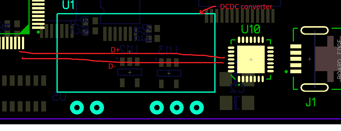
RKZ0505D is a DCDC converter which has maximum 85kHz internal switching frequency. It is placed as large surface of it placed directly on PCB.
If USB data lines pass under plastic package of DCDC converter, Does any unexpected disturbance occur on USB data signals because of switching ?
NOTE1: Signals of USB on TOP layer
NOTE2: DCDC converter placed on TOP mechanically

-
\$\begingroup\$ The short answer; it is highly likely to interfere with USB, which is pretty brittle (for D+ and D- lines in particular) in the first place. \$\endgroup\$– Peter SmithCommented Feb 22, 2019 at 17:21
-
\$\begingroup\$ There is a mistake in the figure: lines should be UART TX/RX, instead of D+/D-. I mean, between Fpga and UART IC. \$\endgroup\$– Berker IşıkCommented Feb 22, 2019 at 18:53
-
\$\begingroup\$ Even worse - UART Rx and Tx are non-differential signals. \$\endgroup\$– Adam LawrenceCommented Feb 22, 2019 at 20:25
1 Answer
I suggest a good ground barrier between any signals near the DC-DC converter unless you are expert electromagnetic coupling design for PCB The unknown is mutual inductance and the capacitance between DC pulse and USB transition current lines.
This means ground planes and guard tracks are necessary. The ground barrier diverts E-field noise along with Gnd guard tracks for co-planar de-coupling noises. Controlled Impedance is needed above USB 1.
You have 3 choices;
1) Model it with Maxwell EMC software or crosstalk from lumped circuit model using Saturn PCB Toolkit
2) Breadboard it or make a prototype and measure phase jitter margin in picoseconds on USB2 or USB3 error rate.
3) Do nothing, cross your fingers and learn from experience about crosstalk on logic signals!
But this question begs the need for specs on Signal risetime and jitter tolerance and nearby crosstalk from supply rated at 150mVp-p @ 20MHz
Need your Specs
The transition current noise of a DCDC and its EMI noise will overlap with USB data spectrum up to 10MHz so that's like asking will it be quiet, if I live beside the train tracks, know the audio spectrum can interfere.
The UART signals from 5V logic is 50 to 66 Ohms unbalanced ought to have controlled impedance and well-guarded on all sides (top/bot. and coplanar by ground signals and perfectly balanced to attenuate this. (CMRR using balun) 3.6V logic is 25 to 33 Ohms.
-
\$\begingroup\$ I think, impedance matching needs between Connector and IC not for red lines in the figure. Red lines are Uart signals. \$\endgroup\$ Commented Feb 22, 2019 at 19:44
-
\$\begingroup\$ If red is UART then UART is a CMOS 25~50 ohm unbalanced logic signal. so guarding may be necessary \$\endgroup\$– D.A.S.Commented Feb 22, 2019 at 19:47
-
\$\begingroup\$ Could you show an example source document in the style you mentioned, guarded uart traces. \$\endgroup\$ Commented Feb 22, 2019 at 19:58
-
\$\begingroup\$ you mean can I look for you? What is your jitter tolerance? \$\endgroup\$– D.A.S.Commented Feb 22, 2019 at 20:02
-
\$\begingroup\$ and signal slew rate? V/ns ? noise is 150mVp-p @ 20MHz BW Is it a USB 2.0 Full Speed device (12Mb/s) as opposed to a USB 2.0 High Speed device (480Mb/s).? THis matters and needs to be added to question \$\endgroup\$– D.A.S.Commented Feb 22, 2019 at 20:08
