2
\$\begingroup\$

I would like to use one of my extra SDRAM bank pins to drive some LEDS. I was thinking about using a mosfet, but considering that I'm only looking at driving a LED, it seemed like a bit much.

So what about this? If I configure the FPGA pin to be open drain, then will this work? I did do a search around here but there isn't anything about this particular configuration. LED forward voltage is 2V typ 2V5 max. Led load current is 6mA.
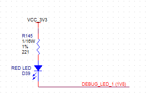
LED

Here is my backup MOSFET cct, but considering it's a 0.5W device, it seems like overkill for this particular application.
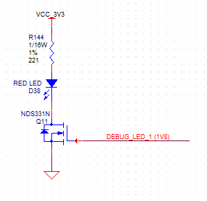
Mosfet

Mosfet on threshold voltage is 0.7V typ and 1V max, ID is 1A when VDS is 1v5, so I think that the 1V8 should turn the mosfet on enough. It looks like the resistance is ~1.5ohm, so it's definitely on enough at VDS is 1V8.

Which is better? Is there a reason why I should go with the mosfet, even if it's a higher-power device?

\$\endgroup\$
5
  • \$\begingroup\$ How bright does the LED need to be? A high-brightness red LED will be visibly illuminated even at only 1.8Vf. If this is just for debugging, I don't see why you need the mosfet at all. \$\endgroup\$ Commented Jan 31, 2013 at 5:28
  • \$\begingroup\$ Remember, LEDs aren't a binary thing, with no light emitted below the rated Vf. \$\endgroup\$ Commented Jan 31, 2013 at 5:28
  • \$\begingroup\$ Not really bright, these LEDs are rated at 20mA max and I'm running them at 6mA. \$\endgroup\$
    – stanri
    Commented Jan 31, 2013 at 5:30
  • \$\begingroup\$ If you have any on hand, apply 1.8Vf with a ~50Ω resistor in series, and see if they're bright enough for your application. If so, just drive them with the IO pin directly. \$\endgroup\$ Commented Jan 31, 2013 at 5:31
  • \$\begingroup\$ I'd like to be able to drive these above Vf so that I have better brightness control. I don't have any on-hand to test at the moment. \$\endgroup\$
    – stanri
    Commented Jan 31, 2013 at 5:44

5 Answers 5

3
\$\begingroup\$

The only reliable and bullet-proof method is to use the MOSFET. I can tell you that without a doubt that the MOSFET will work. But I cannot say the same thing for the open drain pin version.

You may be able to get the LED to light using an open drain pin, but it also might turn on and stay on too. Or the FPGA pin might get destroyed. Or it when you turn it off, it might only get dim and not turn off entirely. A lot of this depends on the FPGA (which you didn't tell us what it is), the exact type of LED, and probably the phase of the moon.

The "signal path" that keeps the LED lit (dimly) when it should be off is: +3.3v -> Resistor -> LED -> FPGA Pin -> ESD Protection Diode -> +1.8v. On the surface this seems unlikely since Vf of both the LED and the protection diode is greater than 3.3v-1.8v. But you have to remember that Vf decreases as the current through the diode decreases. So even in this circuit, there could be a small amount of current flowing. Of course, the question then becomes, "at some small amount of current, will the diode be turned on?" And that question is very dependant on the diode itself.

Using the MOSFET approach has none of these issues. If I were designing a product, I would not take shortcuts and instead use the MOSFET approach.

\$\endgroup\$
2
\$\begingroup\$

The first option will work fine with an open drain FPGA pin, so long as the LED does not fail into a short: If this happens, the FPGA's ability to withstand 15 mA at 3.3 Volts will be the worst-case risk exposure.

As has been pointed out in comments, even operating the LED at 1.8 Volts with open drain should give visible output; whether that is sufficient for acceptable PWM variable intensity performance can only be determined by trying it out, and replacing the LED with a red LED (lower Vf) at worst.

\$\endgroup\$
3
  • \$\begingroup\$ Is a LED failing with a short likely enough to be a concern? Not arguing with the answer just it's an interesting possibility I've never though to cover before in my designs. \$\endgroup\$
    – PeterJ
    Commented Jan 31, 2013 at 6:10
  • \$\begingroup\$ @PeterJ Given that it has never happened to me, my personal thought when writing the answer was "Not likely". However, it is listed as a possible failure scenario in various documentation. I can see that a solder bridge, or contacts bonding short, might happen. \$\endgroup\$ Commented Jan 31, 2013 at 6:12
  • 2
    \$\begingroup\$ The first option, using an FPGA pin as open collector, probably won't work. It depends on the FPGA, but most modern FPGAs are only good for the VCCIO that is being used. So if the pin is setup for 1.8v IO, then feeding it 3.3v is bad. It will cause some current to flow through the protection diode, probably lighting up the LED somewhat dimly in the process. \$\endgroup\$
    – user3624
    Commented Feb 10, 2013 at 22:16
1
\$\begingroup\$

David Kessner's answer explains why connecting directly to an FPGA pin is risky.

But you say the NDS331N FET seems like "overkill". To me that suggests you find the part is either too costly or takes too much board area for the functionality it provides.

In either case, you can consider looking for a FET in a smaller package. SC-70 is about 1/2 the size of the SOT-23. SC-89 is about 1/4 the size of SOT-23.

NTE4153N is one I found after a quick search. SC-89 package (or SC-70 as the NTA4153N). 1.1 V threshold. 700 mOhm Rds-on at 1.8 V gate voltage, and able to sink 100's of mA.

Another option, if you have multiple LEDs to drive, is to use an external open-drain buffer chip instead of individual FETs. A drawback of this approach is I wasn't able to find (in a few minutes searching) a part guaranteed to be able to sink 8 mA when powered with a 1.8 V supply. For example, TI's SN74LVC06A specifies 4 mA sink capability at 1.65 V supply and 8 mA at 2.3 V, so you're left to infer that it's slightly overloaded by 6 mA at 1.8 V. But if you can live with slightly less drive current, it's a part that can drive 6 LEDs, available in a package only 30% bigger than the SOT-23 of your FET.

\$\endgroup\$
0
\$\begingroup\$

Traditional red LEDs were about 1.7V forward. Why the newer ones are about 2V I'm not sure; perhaps newer semiconductor materials are cheaper/more efficient/easier to use.

But maybe older red LEDs are still available? Farnell search options include Vf=1.6 or 1.7V - and funnily enough at 1.6V they all appear to be red - so if you aren't fussy about the colour and select one of these you should be fine.

You only have 0.2V to drop across the resistor, so aim for (say) [email protected] and expect some variation in brightness.

\$\endgroup\$
0
\$\begingroup\$

These look like they'll draw 10mA @ 1.8V and produce 50% of the brightness of their 20mA "rated current"

http://www.farnell.com/datasheets/68768.pdf

I would think that would be bright enough for "debug LEDs" with only 2-4mA.

(A MOSFET looks like overkill for the other option - any old NPN bipolar should do the job easily.)

\$\endgroup\$

Your Answer

By clicking “Post Your Answer”, you agree to our terms of service and acknowledge you have read our privacy policy.

Not the answer you're looking for? Browse other questions tagged or ask your own question.