1
\$\begingroup\$

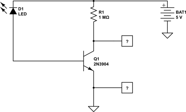
I've been trying to make some cheap light sensors using some coloured LEDs and am using the schematic below. The idea is to hook up a bunch of LEDs (Red, Green, Blue etc.) to try and get an idea of the light wavelengths that they are being exposed to.

I've set up the circuit and am testing the voltage across the 2n3904 (using these since I had some on hand) at the points represented by the [?]. I've tried a few different resistors (100kOhm, 440kOhm, and now 1MOhm playing around with the gain). Power supply is from a 5v 3A mains adapter.
schematic

simulate this circuit – Schematic created using CircuitLab

This is what the scope output looks like when its dark: This is what the scope output looks like when its dark This is what it looks like when it is uncovered (i.e. daylight) This is what it looks like when it is uncovered (i.e. daylight)
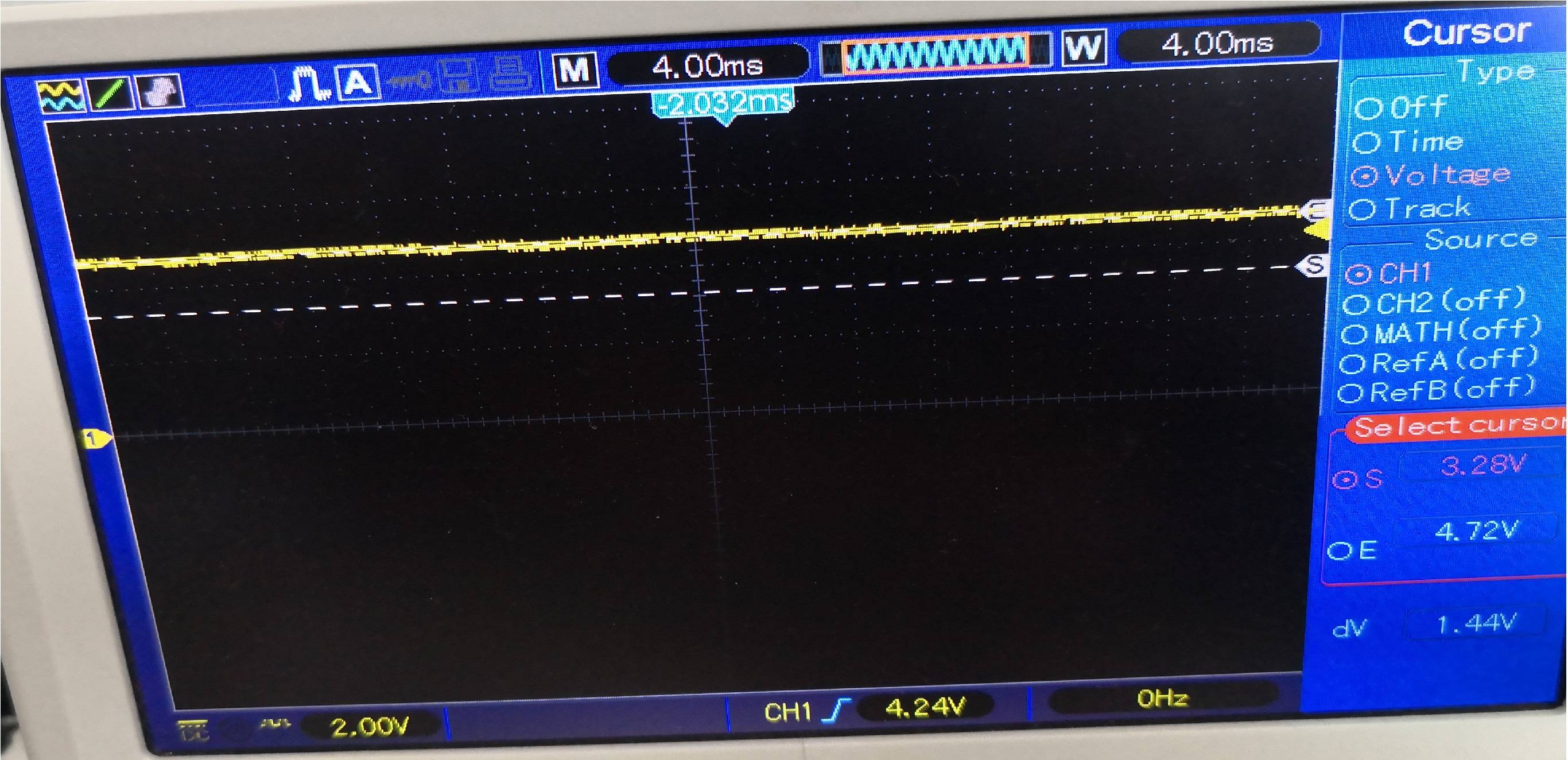
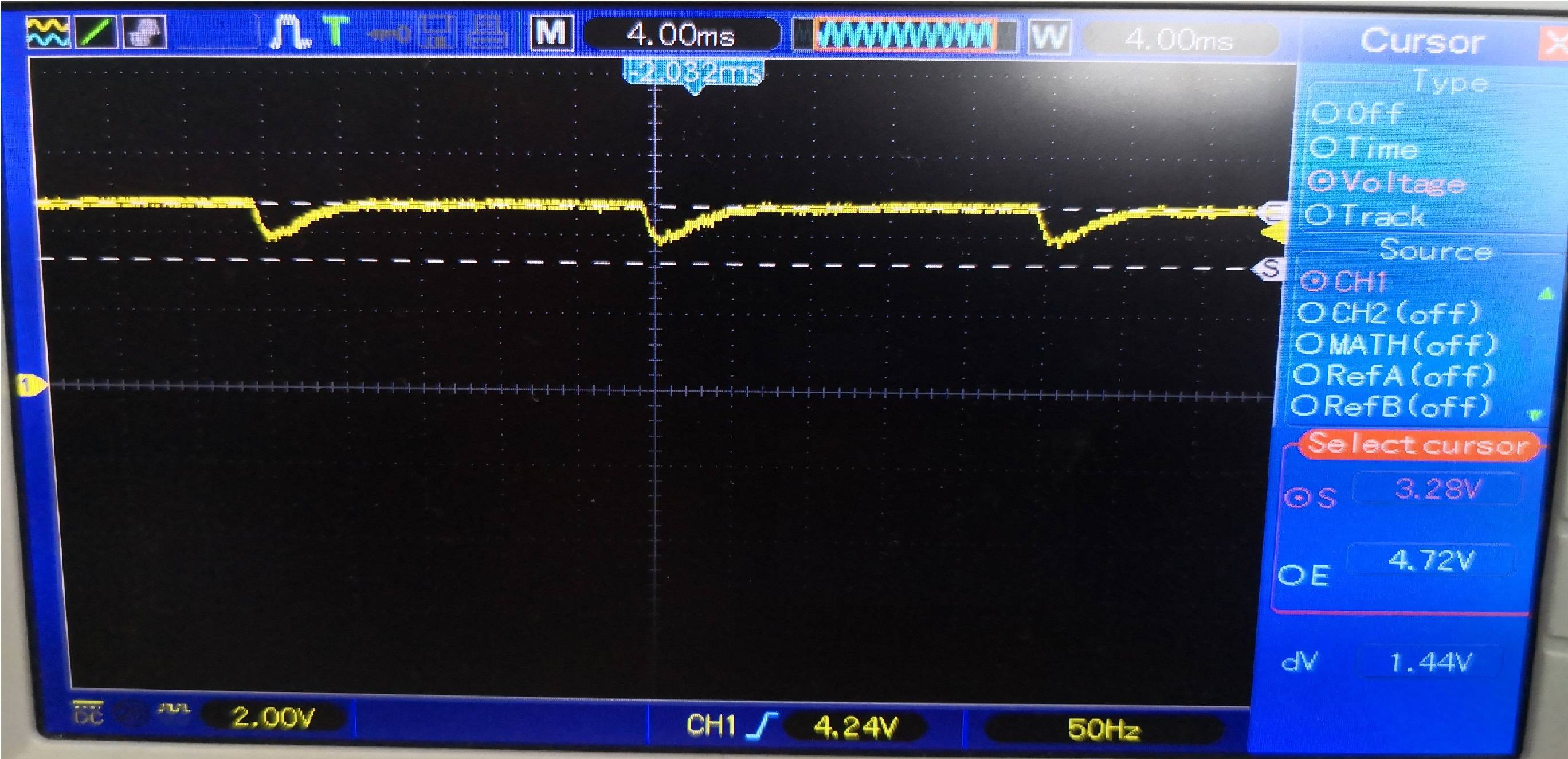
If I put a light source right on top of the LED, the signal minima drops to 0V. I was expecting a 0v DC signal in the dark which would max out at 5v as the LED is exposed to light.

Are my scope traces normal?

If not, what am I not (read: incorrectly) considering in this circuit.

\$\endgroup\$
5
  • \$\begingroup\$ the light source \$\endgroup\$
    – jsotola
    Commented Jun 4, 2021 at 15:22
  • \$\begingroup\$ I'm sorry, could you expand on that statement please? What's the issue with the light source? \$\endgroup\$
    – Letshin
    Commented Jun 4, 2021 at 15:29
  • 1
    \$\begingroup\$ I'd expect near 0V in bright light, and near 5V in dark. LED generates more photocurrent in bright light so it turns transistor more on. Why do you expect it the other way around? \$\endgroup\$
    – Justme
    Commented Jun 4, 2021 at 15:33
  • \$\begingroup\$ Yes, your 'scope traces make sense. The common-emitter transistor is an inverting voltage amplifier - photocurrents cause more collector current to flow....this will cause collector voltage to fall closer to ground. \$\endgroup\$
    – glen_geek
    Commented Jun 4, 2021 at 15:35
  • \$\begingroup\$ OK, thanks.... That clears some things up. I'd misremembered that and so that makes this a stupid question. \$\endgroup\$
    – Letshin
    Commented Jun 4, 2021 at 15:41

1 Answer 1

1
\$\begingroup\$

Are they normal, yes. The LED provides current to the transistor, which "turns the transistor on more" and when the transistor is on, it pulls the voltage on the node between the transistor and 1MegΩ resistor down.

And yes this is the expected output, there is an article here that shows a similar output with a similar circuit:

enter image description here
Source: https://wiki.analog.com/university/courses/electronics/electronics-lab-led-sensor

\$\endgroup\$

Your Answer

By clicking “Post Your Answer”, you agree to our terms of service and acknowledge you have read our privacy policy.

Not the answer you're looking for? Browse other questions tagged or ask your own question.