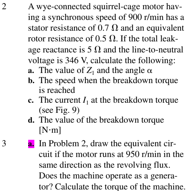
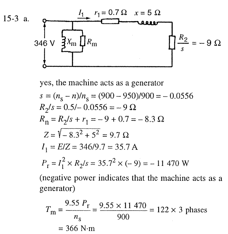
That was not a machine made of copper wire, steel and insulator material. That was a circuit which which would behave resembling the behaviour of a real machine when only the voltage and current are observed at different rotation speeds.
The negative resistance is the imagined object (as imaginary as the rest of the circuit) which will output energy instead of dissipating it if the rotation speed was higher than the synchronous rpm. At lower speeds than the synced rpm the resistor would be positive and dissipates as much energy as what's got from the motor axis to a mechanical load.
R2 in the apparent resistance formula R2/s is the real rotor resistance, but reduced to be seen in the stator side like shorted seconary of a transformer could be seen in the primary circuit.
Shortly: The negative resistor is the circuit element which is needed to make the approximate equivalent circuit to output energy as negative dssipation (I^2)R. In actual generator that energy is got from the external Machine which rotates the generator.
Btw. Negative resistors are not available as components but they can be built as circuits and many amplifying or oscillating components can be modeled with negative resistance in their equivalent circuit.


