0
\$\begingroup\$

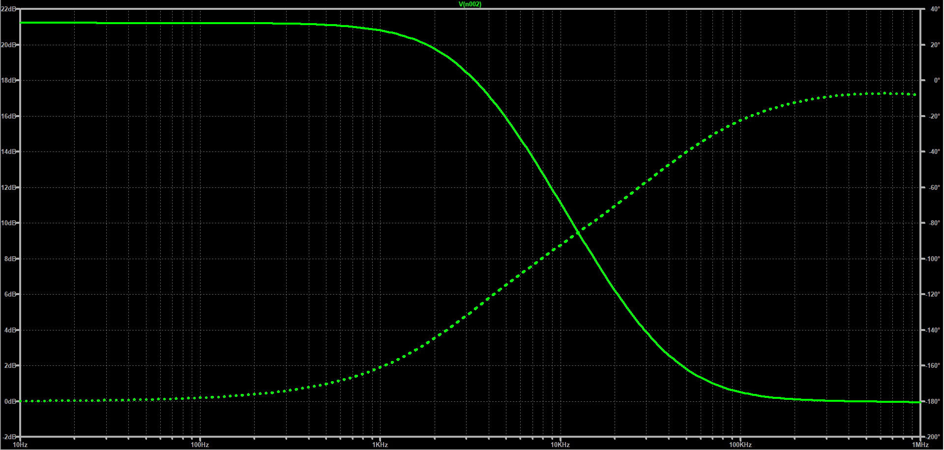
I've been trying to invert the phase response of a non-inverting low pass filter by using a "negative resistor" (-5000 ohms,) which is achieved by the simulation below (bode plot + circuit): enter image description here
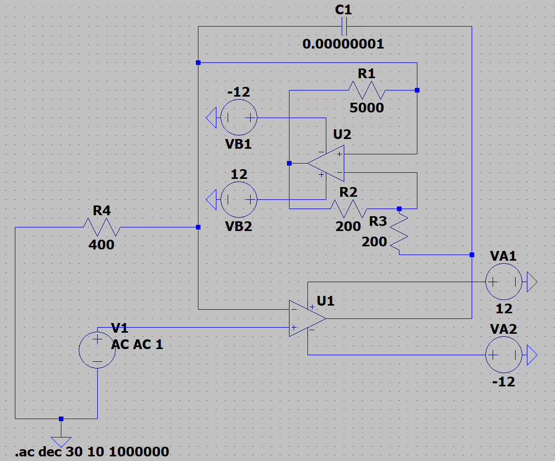
enter image description here

When I built the circuit using LM358 op amps, the NIC makes the original low pass filter circuit lose its output signal.

I've also noticed that the NIC makes the power supply for the first op amp, U1, behave erratically - i.e. the negative voltage supply pings left when I turn on the positive voltage supply.

I use a different power supply for each op amp, and the power supply pins on both op amps have decoupling capacitors in place.

Could the NIC circuit just not be usable in the actual circuit?

\$\endgroup\$
8
  • 3
    \$\begingroup\$ Have you tried doing a transient simulation in order to see what the circuit is actually doing? \$\endgroup\$
    – Dave Tweed
    Commented Jun 10, 2021 at 14:46
  • 2
    \$\begingroup\$ The phase is positive, that means unstable. \$\endgroup\$ Commented Jun 10, 2021 at 14:56
  • \$\begingroup\$ I've done an actual bode plot of the non-inverting low pass filter without the NIC using a function generator and an oscilloscope to plot both the gain and phase response via comparing the input signal with the output signal. However, when the NIC is used instead of a 5000 Ohm resistor, the output signal disappears. \$\endgroup\$
    – tupsman
    Commented Jun 10, 2021 at 15:09
  • 1
    \$\begingroup\$ As Dave says, you should do a transient simulation before doing an AC analysis. The latter only makes sense if the circuit is behaving more-or-less linearly. \$\endgroup\$ Commented Jun 10, 2021 at 19:56
  • 1
    \$\begingroup\$ Please use engineering prefixes! \$\endgroup\$
    – winny
    Commented Jun 10, 2021 at 19:57

2 Answers 2

1
\$\begingroup\$

Trying to grasp the idea behind your circuit first I see an op-amp non-inverting integrator (R4, C1 and U1)... then a current-inversion NIC (INIC) injecting a current through the capacitor that is proportional to the voltage across it.

Really, the INIC is floating and it should be supplied by separate voltage sources VB1, VB2. The two equal resistors R2, R3 and the op-amp U2 form a non-inverting amplifier with a gain of two... but I think these 200 ohm resistances (400 ohm voltage divider in the negative feedback) are too low.

\$\endgroup\$
0
\$\begingroup\$

A good start would be to put in all the parasitics into LT spice and make the simulation more like the real world. Wires have inductance and resistance, this can be calculated. If your building this circuit on a breadboard, you'll have a lot of capacitance in the pF's range between tracks and contact resistance.

Capacitors also have a small amount of inductance in the nH range and a high value of resistance.

The last thing is noise. Put in a noise generator and see what the circuit does. You can then make the circuit match the real world (a bit more) before building.

\$\endgroup\$

Your Answer

By clicking “Post Your Answer”, you agree to our terms of service and acknowledge you have read our privacy policy.

Not the answer you're looking for? Browse other questions tagged or ask your own question.