I am trying to build a low pass filter circuit from the LM358 datasheet from TI. Looking at the pinout and building the circuit I cannot get something basic like this filter to work. I have everything connected properly, with the GND pin (pin4) connected to the negative power rail and the VCC pin (pin8) connected to the positive rail. I've been scratching my head over this the past couple hours, any help would be much appreciated.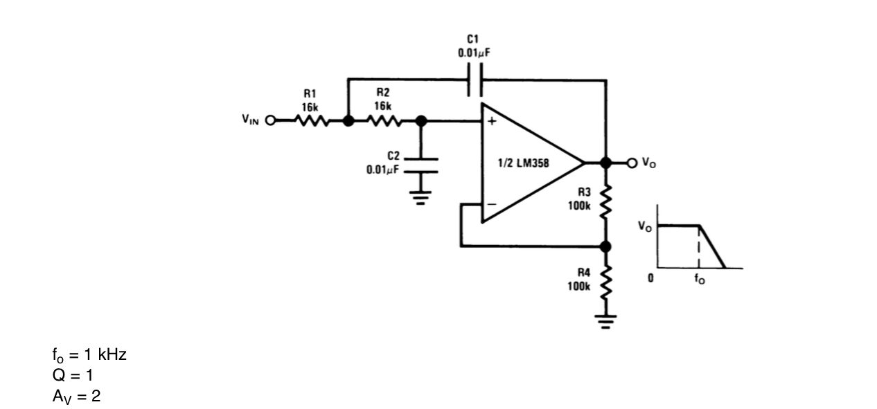
-
\$\begingroup\$ What power rails are you using? Your title implies a single rail and you say you´ve connected "GND pin (pin4) connected to the negative power rail", but is that ground, or a negative rail? The circuit above will only work if there are 2 rails and (separate) earth. \$\endgroup\$– J. LittleCommented Dec 10, 2014 at 19:06
-
\$\begingroup\$ I guess I am confused as to what exactly GND is. My mistake, When I say negative rail what I meant was the return path of the power supply itself- I am only using one power supply. In the schematic I posted all the GND symbols are tied to the return path of my power supply. Now the pinout for from the datasheet says pin4 is the IC's GND, so I have the that connected to the return path of my power supply and using that as my reference. Is that wrong? \$\endgroup\$– Rio SchadCommented Dec 10, 2014 at 19:20
-
\$\begingroup\$ You need a dual supply, like + and - 5V. When this part was new, it was common to use +-18 and +-15. You can use two simple supplies as long as they are isolated. Connect + of one to - of the other and that connection point is called GND in the world of op-ampery. Or use two batteries. If you make your own or have an easy source of AC at 8 or 10V RMS, make a half wave voltage doubler with diodes and caps. This was the lowest cost way to do it in the old days. There are also single chips that can "invert" the positive supply and provide some "negative" that are handy. \$\endgroup\$– C. Towne SpringerCommented Dec 10, 2014 at 21:41
-
\$\begingroup\$ 1) If you are asking about a single-supply circuit, it would help tremendously if you drew your supply connections in the schematic, 2) what does "doesn't work" mean? What's the input? What's the output? What were you expecting? \$\endgroup\$– Phil FrostCommented Dec 10, 2014 at 21:42
2 Answers
You need to create a false mid-point for your amplifier. This can be done with two resistors and capacitors: -
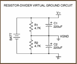
Or, better still using an op-amp like this: -
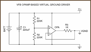
Now, to make your input signal compatible, you'll need to feed it via a series capacitor like 10uF. This will remove the dc level from your input signal: -
If it is important to maintain the dc level then you have to use two power supplies with the centre point connected to ground.: -
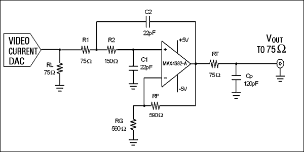
Ignore the values, RL, Cp and RT - this is just an example.
As it stands, the op amp cannot handle any input below 0 volts, and about half of any AC input will be in this range, so it's no wonder the circuit doesn't work.
Try this
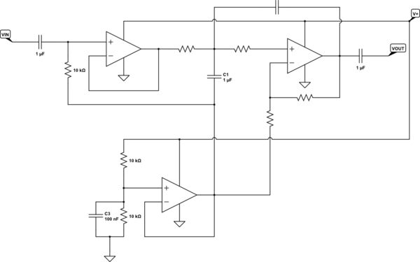
simulate this circuit – Schematic created using CircuitLab
The lower op amp creates what is known as a pseudoground, and this is the reference point for the other two op amps. The pseudoground is commonly set halfway between the supply and ground in order to allow symmetrical voltage swings. The left-hand op amp is necessary to isolate the input DC level - without it the DC filter gain would saturate the filter unless you were very lucky.
Note that this loses your DC level on the input signal. As long as the input signal ground and the power ground are the same (and I expect this is true), this will generally be the case. There are ways to get around this, but I expect that this is a good start, given your apparent skill level. If you really do need to preserve DC, get familiar with this circuit, then ask another question.
