1
\$\begingroup\$

It has been quite a while since I've used a breadboard or looked at circuits (probably 20+ years since high school and college physics.)

I'd like to think I know how they work, but something isn't clicking for me.

I'm working on Ben Eater's 8 bit computer, starting out with the clock. Specifically the astable 555 timer-based clock, the first module.
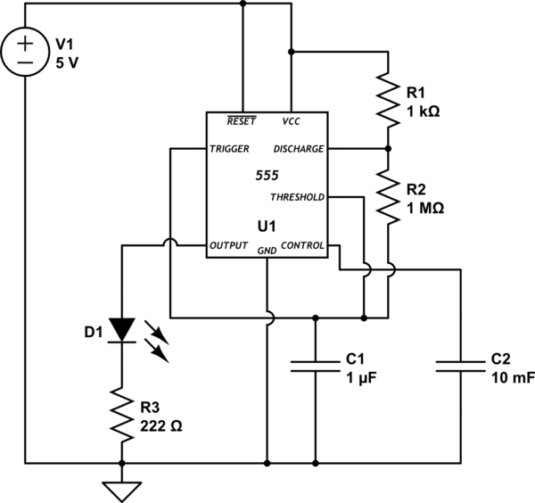
Astable 555 timer circuit

schematic

simulate this circuit – Schematic created using CircuitLab

I've connected the breadboard with a 5V connection and have a 'canary' LED at the bottom of the breadboard with a wire connection to ground and a 220 ohm resistor to 5V that lights up, just to make sure there isn't an issue with the power.

The issue is that the LED doesn't oscillate. It just stays on.

I think that means potentially that there's an issue with the capacitor, but I've tried multiple capacitors of the same size, and tried one that was larger just to check.

Based on the calculator at allaboutcircuits.com, I should have a cycle time of 0.7s for the 1uF capacitor and 7s for the 10uF capacitor. But again, just getting a constant on.

I wondered if it was cycling so fast I couldn't see it, but according to the calculations that shouldn't be the case. I've also tried a couple of other resistors just to check and got the same thing.

What I've tried:

  • Different capacitors of the same size
  • A capacitor of the same size
  • Different 555 chips (including purchasing some additional chips)
  • Different LEDs
  • Different parts of the breadboard (in case part of it was bad)
  • Different resistors in R1 and R2
  • Making sure positive and negative were correctly attached to the breadboard
  • Making sure the capacitor '-' is plugged into the negative on the breadboard (blew a capacitor before I figured that one out)

There's a similar question asked and answered on this board ('Astable 555 circuit not oscillating'). I spent the last couple days, a total of 2-3 hours, working through the posted answers on that question and it doesn't appear that any of those answers solve my issue, though I could certainly be incorrect as I'm new at this.

I've compared my circuit to other astable 555 circuits and everything looks fine, just not sure what I'm doing wrong.

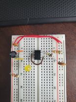
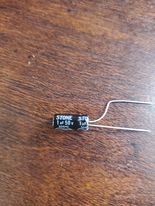
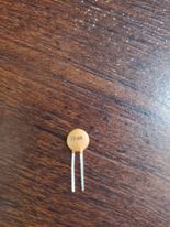
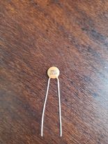
Large capacitor - C1 Small capacitor - Not shown Small capacitor - C2

\$\endgroup\$
5
  • 3
    \$\begingroup\$ Is C2 actually 10mF (10,000uF) or is it 10nF (0.01uF)? Are you sure C1 is actually 1uF and not, say, 1nF? Maybe photos of the parts would help.. \$\endgroup\$ Commented Jun 23, 2021 at 0:01
  • \$\begingroup\$ I would guess that the LED appears to be always on however it is switching faster than the eye can follow. It is taking advantage of a property of the eye called persistence. \$\endgroup\$
    – Gil
    Commented Jun 23, 2021 at 1:31
  • \$\begingroup\$ If C2 really is 10 mF it willl take a long time for it to charge to a stable voltage. \$\endgroup\$
    – Oskar Skog
    Commented Jun 23, 2021 at 6:50
  • \$\begingroup\$ I've added some pictures of the parts you're asking about. C2 is .01uF, thought I got the conversion correct, but apparently not. \$\endgroup\$
    – Mike Felts
    Commented Jun 23, 2021 at 11:33
  • \$\begingroup\$ Sorry, .01uF is the cap I have across + and - (not shown on the schematic as I couldn't figure out how to show it). C2 is .1uF (also pictured above). \$\endgroup\$
    – Mike Felts
    Commented Jun 23, 2021 at 11:49

2 Answers 2

2
\$\begingroup\$

To start, add a 10 uF cap and 0.1 uF cap in parallel from pin 1 to pin 8 with the shortest possible leads. This is for power supply decoupling. The innards of a 555 are two analog comparators, and they expect a low impedance power source. Test the circuit.

Next, decrease R2 to 100K, increase R1 to 10K, and increase C1 to 10 uF. This is a test to see of the 555 is unhappy with the timing component impedances. A bipolar 555 does not work well with very high resistances or very high capacitances.

\$\endgroup\$
1
  • \$\begingroup\$ I'll have to pick up some additional resistors to try this out. I have 10uF caps, but only have 222, 1k, and 1M ohm resistors (really just what's needed for the kit). I'll try it in a couple days. Thanks for the help! \$\endgroup\$
    – Mike Felts
    Commented Jun 23, 2021 at 11:41
1
\$\begingroup\$

The cap value in your diagram is a bit off. 10mF (10 millifarad) = 10,000uF. I don't think that was your intention.

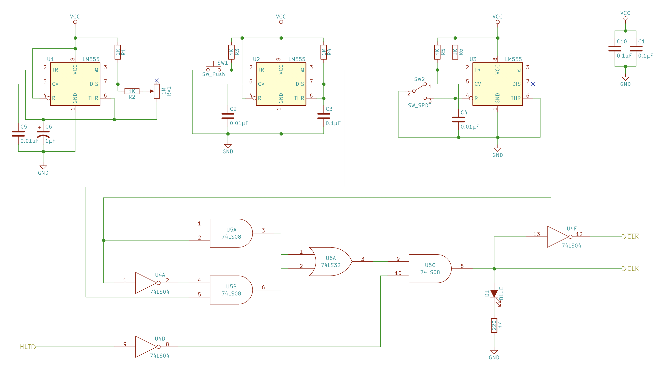
Anyway, I checked out Ben Eater's actual schematic for this thing.

enter image description here

Schematic from here: https://eater.net/8bit/schematics

Notice the 555 on the left (U1). The cap is 1uF, a variable pot with a max of 1M, and a 1k in series with the wiper. Turns out this matters.

I did a quick sim with 1uF and R2 set as follows, modeling the schematic:

  • 1.001M (max pot) = 0.71 Hz
  • 501k (mid pot) = 1.42 Hz
  • 1k (min pot) = 416.6 Hz - limited by the resistor on the wiper

As you can see this control will be highly non-linear. Maybe with a log taper pot it would be less heinous.

The rest of the clock stuff is for single-step. He's using U2 as a single-step one-shot and U3 as S-R flop to debounce the run/stop switch. All okay, I guess, though asynchronously switching the clock is bad as it can cause a glitch.

Finally, his diagram includes a 0.1uF bypass cap on CV (control voltage.) Recommended.


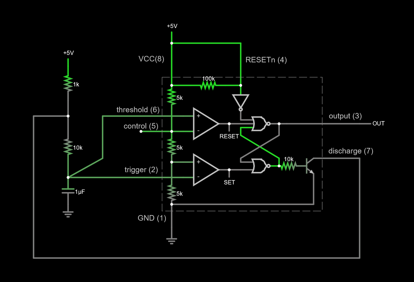
As a way of explaining how the 555 works, here's a simulation showing its internals (simulate it here):

enter image description here

What's supposed to happen is the capacitor charges up, when its voltage reaches 2/3 VCC the upper comparator fires and resets the latch, starting the process of discharging the cap. When the cap voltage reaches 1/3 VCC, the latch is set by the lower comparator, stopping the discharge and allowing the cap voltage to rise again.

So as it oscillates, the cap voltage should be ramping between 1/3 and 2/3 VCC.

\$\endgroup\$
9
  • \$\begingroup\$ The schematic he shows is for the final form. I think the only thing I've switched out is the variable pot (I'm going based on an intermediate part of his 1st video) as I wanted to make sure that wasn't the issue. I've tried it with the variable pot in place as well (with the 1k resistor inline) and it didn't make a difference, so wanted to remove variables to troubleshoot as it -should- be oscillating without the variable pot in place of R2. \$\endgroup\$
    – Mike Felts
    Commented Jun 23, 2021 at 11:37
  • \$\begingroup\$ I have a .1uF cap on CV (C2, the one I marked as 10 mF by mistake) and also have a .01uF cap across positive and negative (not shown in the schematic because I couldn't figure out how to draw it). \$\endgroup\$
    – Mike Felts
    Commented Jun 23, 2021 at 11:39
  • \$\begingroup\$ One thing you can try is to connect the 1M to output instead of discharge. This also functions as an astable. Other than that, check ground, power, etc. 1uF and 1M are acceptable values for the 555. \$\endgroup\$ Commented Jun 23, 2021 at 14:58
  • \$\begingroup\$ Thanks for the options hacktastical! I tried spreading the 1M resistor across the chip so it reached discharge (thankfully I hadn't trimmed the wires yet) and it didn't change anything; the LED is still constantly on. \$\endgroup\$
    – Mike Felts
    Commented Jun 23, 2021 at 19:38
  • \$\begingroup\$ Is pin 4 (RESETn) tied to VCC? If RESETn is low, the output will be high. \$\endgroup\$ Commented Jun 23, 2021 at 19:40

Your Answer

By clicking “Post Your Answer”, you agree to our terms of service and acknowledge you have read our privacy policy.

Not the answer you're looking for? Browse other questions tagged or ask your own question.